Learn the process flow of characteristic-based forecasting (CBF) in SAP Advanced Planning and Optimization (SAP APO). Follow a step-by-step procedure to configure the master data, create CBF-relevant configuration, release the forecast at the characteristic level from demand planning, and interpret the results.
Key Concept
Demand Planning (DP) in SAP Advanced Planning and Optimization (SAP APO) helps to generate forecasts based on historical values. By using characteristic-based forecasting (CBF) in DP, you can forecast not only at the product but also at the characteristic level. For example, in the automobile industry you can have several variants of a product (e.g., a motorized bicycle) based on color, engine, or transmission. Therefore, the planner needs to forecast demand not only at product level but also at the characteristic level. In SAP terminology, different features of a product such as a motorcycle are called characteristics (e.g., color or engine), and each characteristic has different values assigned to it known as characteristics values.
SAP Advanced Planning and Optimization (APO) Demand Planning (DP) helps you to carry out the forecasting process. You can use statistical forecasting techniques, such as the constant, trend, and seasonal models with different forecasting models. The output of the DP process is the demand plan (forecast). The demand plan is used to generate planned independent requirements at required locations for specific time periods.
Characteristic-based forecasting (CBF) is a feature of DP with which planners can not only define their forecast at the product level but also can segregate the forecast for a product at its characteristic level.
In demand planning without CBF, planners perform planning at the stockkeeping unit (SKU) or product level, but they cannot see the product’s forecast at the detail characteristic level. Therefore, CBF has been introduced to incorporate this feature in DP. This is particularly useful in the automobile and high-tech industries in which you can have multiple variants of the same product and the number of combinations can go from a few hundreds to thousands. Obviously, not all combinations are relevant for the forecasting process. CBF provides you with the flexibility to restrict the characteristics used in CBF to those that are important for planning purposes.
Business Scenario
Consider an example of a motorcycle manufacturer that builds motorcycles with various colors, with different engine capacities, and with different wheel types. In this case one of the models of the motorcycle is the product, but color, engine, and wheel types are its characteristics. With the help of the CBF feature, planners can see the demand not only at the motorcycle level but also at the segregated demand level in which various colors, engine capacities, and wheel types help them complete an accurate forecast.
Figure 1 shows a scenario with product, characteristic, and characteristic value levels.
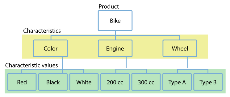
Figure 1
An example of CBF showing product, characteristics, and characteristic values (cc stands for cubic centimeters and is used to describe engine capacity)
To configure CBF for the scenario shown in Figure 1, you need to complete the following steps:
- Location master
- Product master
- Characteristics
- Classes
- Transfer master data from SAP ERP Central Component (ECC) to SAP APO
- Storage bucket profile
- Time bucket profile
- Master planning object structure
- Planning area
- CBF table
- CBF profile and linkage to the CBF table
- Create a CVC
- Create time series objects
- Set up a planning book and data view
- Add forecast values
- Create a consumption group
- Assign a consumption group to the product master
- Release a forecast from DP
- Validate a forecast in the product view
- Interpret the results
Step 1. Set Up Master Data in SAP APO
To use the CBF feature, you need to first create the master data objects. The master data needs to be configured for the following objects:
- Locations
- Products
- Characteristics
- Classes
Location Master
To configure the master data for locations, execute transaction code /SAPAPO/LOC3. Locations in SAP APO are differentiated by location type. Some of the important location types that are frequently used in SAP APO are listed in Table 1.
Location type
|
Description |
1001
|
Production plant
|
1002
|
Distribution center
|
1007
|
Storage location material requirements planning area
|
1010
|
Customer
|
1011
|
Vendor
|
Table 1
Important location types in SAP APO
In the initial screen that appears after you execute transaction code /SAPAPO/LOC3 (Figure 2), enter a name (e.g., PLANT1) in the Location field and a value for the corresponding location type (e.g., 1001) in the Location Type field. Click the Create button.
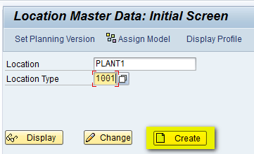
Figure 2
Enter a name and a value
In the next screen (Figure 3), enter a description for the location (e.g., Production Plant – 1).

Figure 3
The Location Master Data screen header
After you enter a description for the location, navigate to the Address tab (not shown), and in the Street Address section, enter the country details (e.g., US) as shown in Figure 4. This data helps the system to allocate the correct time zone.

Figure 4
The Street Address section
After you enter the details shown in Figure 4, click the save icon (not shown). Once the location has been saved, click the back icon to return back to the main screen. Click the Assign Model button (Figure 5) to assign the location to the active model.
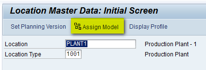
Figure 5
Assign a model in the Location Master Data screen
After you click the Assign Model button, a pop-up screen appears (Figure 6). Enter 000 in the Model Name field to assign the location to active model 000.

Figure 6
Select a model
After you select Model 000, click the assign objects to model icon in Figure 7 and then click the enter icon (the green checkmark beside it).

Figure 7
Assign the object to the model
This action makes the location available to all planning versions. After assigning the location to the model, you see the message shown in Figure 8 indicating that the assignment is made correctly.
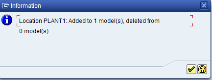
Figure 8
Location master data assignment is successful
Product Master
To configure master data for products, execute transaction code /SAPAPO/MAT1. In the Product Master: Initial Screen (Figure 9), enter a product and location. To do this, click the Product radio button and enter a product name (e.g., BIKE-A). Click the Location radio button and enter a name (e.g., PLANT1). Because you are creating a new product directly in SAP APO, you enter your own product name. Click the Create button highlighted in Figure 9.
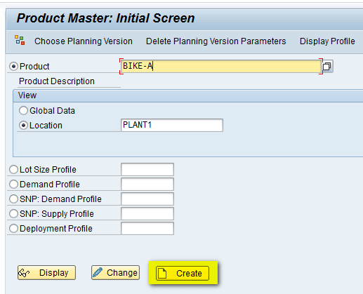
Figure 9
Enter a product and a location in the Product Master: Initial Screen
In the next screen (Figure 10), enter a description in the Product Descrip field (e.g., Bike Model - A) and a base unit of measure in the Base Unit field (e.g., EA, which stands for Each). After you enter these details, you can go to different tabs and assign other parameters as needed. Because you are only defining a product that would be used in DP and forecasting, other parameters are not necessary.

Figure 10
The product master header
After you enter the details shown in Figure 10, click the save icon and then click the back icon to return to the main screen. In the main screen, click the assign model icon to assign the location to the active model (Figure 11).
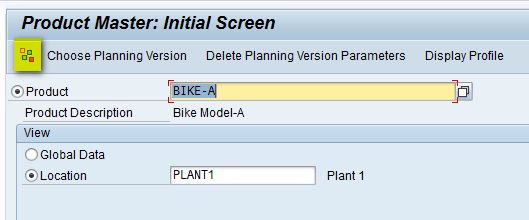
Figure 11
Assign a model
After you click the assign model icon shown in Figure 11, a pop-up screen appears (Figure 12) in which you enter 000 in the Model Name field to assign the product to active model 000.

Figure 12
Assign the product to active model 000
After you select Model 000, click the assign objects to the model icon and then click the green arrow icon beside it as shown in Figure 13.

Figure 13
Activate the assignment
Now you see a screen that displays a message indicating that the assignment is made correctly (Figure 14).
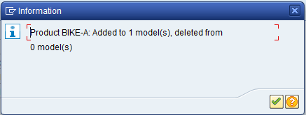
Figure 14
Assignment added to model successfully
Click the green checkmark shown in Figure 14 to display the screen shown in Figure 15. Now you can assign the product to the required planning version for use in planning. Click the Choose Planning Version button.

Figure 15
Choose a planning version
In the pop-up screen (Figure 16), enter 000 in the Plng Version field to assign the product to active planning version 000. Then click the enter icon (the green checkmark).
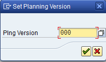
Figure 16
Assign the product to the active planning version
Characteristics
You need to define characteristics that will act as attributes on which you need to do the forecasting. To configure master data for characteristics, execute transaction code CT04. In the next screen (Figure 17), give the characteristic name (e.g., COLORS) and press Enter.

Figure 17
The Characteristics initial screen
In the pop-up screen that appears (Figure 18), click the Yes button.
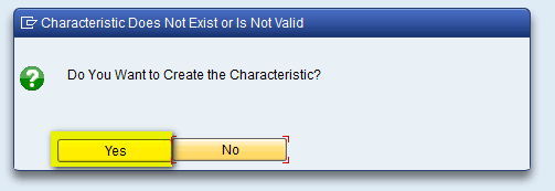
Figure 18
Create a new characteristic
In the Basic data tab of the next screen, enter a description (e.g., Bike Colors), select a data Type from the drop-down list (e.g., Character Format), and enter the number of characteristics (e.g., 20) as shown in Figure 19.
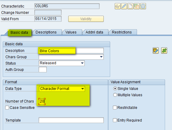
Figure 19
Populate fields for the COLORS characteristic in the Basic data tab
In the Values tab (Figure 20), enter the different characteristic values for the COLORS characteristic and add descriptions. After you enter the values, click the save icon. This action means one of the characteristic colors has been defined and values have been assigned to it.
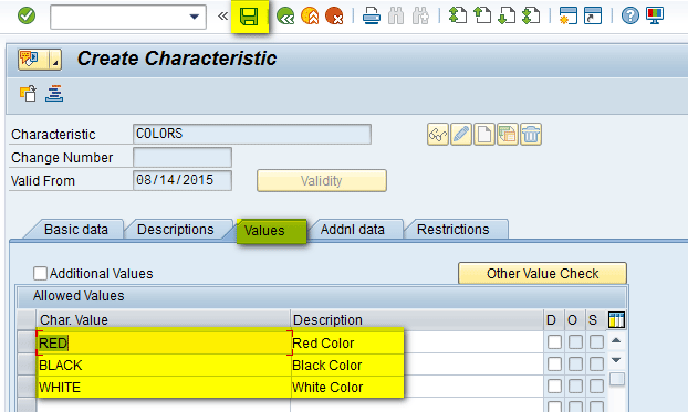
Figure 20
Enter characteristic values in the Values tab
Now follow the same instructions (Figures 17 through 20) to create characteristics for Engine (Figure 21) and Wheels (Figure 22).
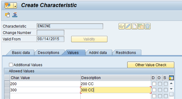
Figure 21
The Engine characteristic
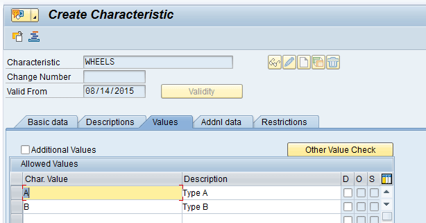
Figure 22
The Wheels characteristic
Classes
You need to define a class that joins together all the characteristics defined in the above steps. To create a class, execute transaction code CL01. In the next screen (Figure 23), enter the class name (e.g., Z_CLASS_BIKE), select an option in the Class type field (in my example, you need to select class type as 012 for characteristic class), and press the Enter key.

Figure 23
Select a class type in the Create Class: screen
In the Basic data tab of the next screen, enter a description (e.g., Bike Class), as shown in Figure 24.
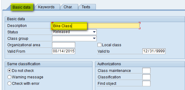
Figure 24
Enter a description
In the Char. tab select all the three characteristics defined in above steps (Colors, Engine, and Wheels) as shown in Figure 25 and click the save icon.

Figure 25
The Char. tab
These steps complete the setup of master data needed to execute CBF in SAP APO. Note that I have created all the master data manually in SAP APO. However, this master data can also be created in ECC and then transferred to SAP APO via the Core Interface (CIF). The diagram in Figure 26 shows the mapping of master data objects between ECC and SAP APO.
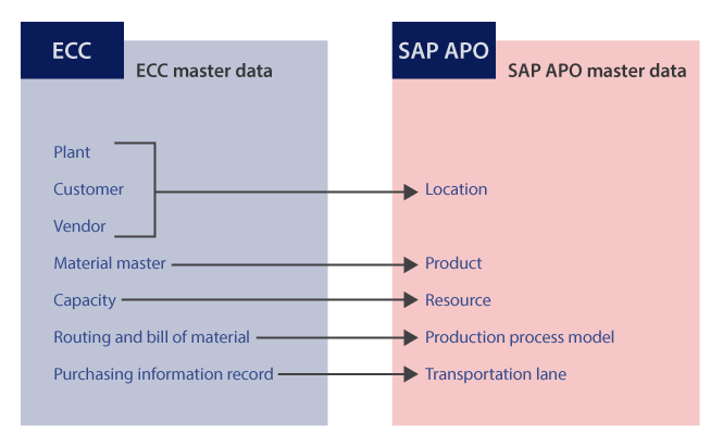
Figure 26
Master data mapping between ECC and SAP APO via CIF
Transfer of Master Data from ECC to SAP APO
It is also possible to create master data in ECC and have it transferred to SAP APO via the CIF. CIF is a standard interface provided by SAP to integrate both master and transaction data between ECC and APO. Integration of master data from ECC to APO is basically a two-step process.
Create and Generate an Integration Model
An integration model is used to describe and select the datasets that you want to transfer. You use an integration model to specify both the SCM target system to which data needs to be sent and the data objects that have to be transferred. To generate and activate the integration model, execute transaction code CFM1 in ECC. In the initial screen that appears (Figure 27), enter names in the Model Name field (e.g. MDATA), the Logical System field — this is the name of the SAP APO system to which the ECC system is connected (e.g., AS1CLNT200) —, and the APO Application field (e.g., CHAR).
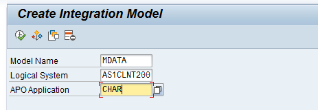
Figure 27
Define the datasets in the Create Integration Model screen
In the same screen, you can see there are different objects that are present (e.g., Materials and Plants). If you want to send Materials from ECC to SAP APO, select the Materials check box and further filter the material based on different parameters (e.g., material name and plant) highlighted in the red box in Figure 28.
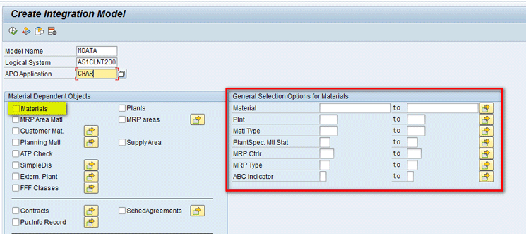
Figure 28
Selection options in the Create Integration Model screen
Now I show you how to transfer characteristics if they are created in ECC and need to be sent to SAP APO. Initially, you need to create the characteristics in ECC by following the steps described in the “Characteristics” section. In my example in the “Characteristics” section, you created three characteristics – COLORS, ENGINE, and WHEELS. Continuing in the same screen (transaction code CFM1), you can scroll down and select the Classes/Charact check box as shown in Figure 29 and then select the highlighted right arrow icon.
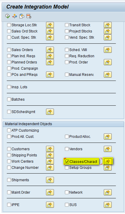
Figure 29
Select characteristics in the Create Integration Model screen
After you click the arrow icon, a new screen appears on the right (Figure 30). Click the right arrow icon.

Figure 30
The Classes and Characteristics section of the Create Integration Model screen
In the pop-up screen that appears (Figure 31), enter the name of the characteristics (e.g., COLORS, ENGINE, and WHEELS) and then click the execute icon.

Figure 31
Enter characteristic details in the pop-up screen
After you click the execute icon in Figure 31, the system returns you to the Create Integration Model screen (Figure 32). At the top of this screen, click the execute icon.
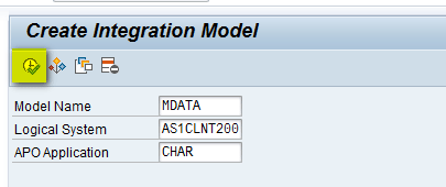
Figure 32
Click the execute icon in the Create Integration Model screen
In the next screen, click the Detail button as shown in Figure 33.

Figure 33
Click the Detail button
This action displays a screen in which you can see names of all three characteristics that have been selected by the integration model (Figure 34). Click the back button to go back to the previous screen.
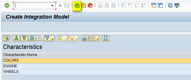
Figure 34
Characteristic details displayed in the Create Integration Model screen
In the next screen (Figure 35), click the Generate IM button.
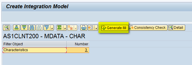
Figure 35
Generate an integration model
After you click the Generate IM button, a pop-up screen displays a message stating that the integration model has been generated (Figure 36). Click the green checkmark icon to proceed.
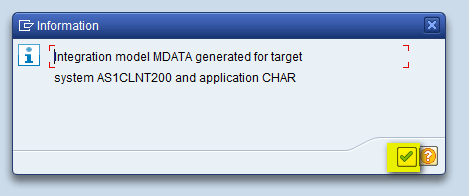
Figure 36
Message indicating that the integration model was successfully generated
Activate the Integration Model
In this step you activate the integration model that you created in step 1. To complete this step, execute transaction code CFM3 in ECC. In the screen that appears (Figure 37), populate the Model, Logical System, and APO Application fields. These names are the same ones that you entered while creating the integration model in step 1. Select the Activate Newest Version radio button and then click the execute icon.
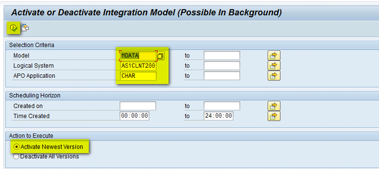
Figure 37
The initial screen to activate the integration model
In the New Status column of the next screen (Figure 38), the green checkmark indicates that the status of the integration model is now active (the Prev. Status column has a red X to indicate that the integration model was inactive.) Click the Start button.

Figure 38
Activate the integration model
This action opens a pop-up screen that displays a message asking you to branch to the application log (Figure 39). Click the Yes button.

Figure 39
A pop-up screen asking to branch to the application log
In the next screen (Figure 40), you can see that all application logs have a green box that shows that CIF transfer is complete and all characteristics have been transferred successfully to the SAP APO system.
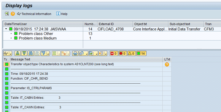
Figure 40
Application logs
You can also see the status of the integration model by executing transaction code CFM4 in ECC. In the screen that appears (Figure 41), enter names in the Model (e.g., MDATA), Logical System (e.g., AS1CLNT200), and Application (e.g., CHAR) fields and then click the execute icon.
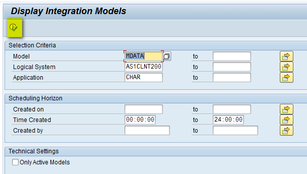
Figure 41
The Display Integration Models screen in ECC
In the next screen (Figure 42), expand the Integration Models and Model nodes (e.g. MDATA), select the Application Name (e.g., CHAR) and double-click it.
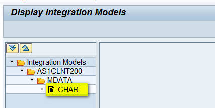
Figure 42
Select the integration model name
This action opens a screen on the right side of the Display Integration Models screen that shows that current status of the integration model is active (this status is indicated by the green checkmark icon in Figure 43.

Figure 43
The integration model displayed as active
You can follow similar steps to transfer other master data objects such as Material and Plant from ECC to SAP APO. Follow the same two-step process as described above with step 1 being the create and generate integration model and step 2 being activating the created integration model.
Step 2. Set Up DP Objects
In this section I explain the steps need to configure DP objects.
Storage Bucket Profile
The storage bucket profile is used to save the data that would be defined in the planning area in time buckets. To define the storage bucket profile, execute transaction code /SAPAPO/TR32. In the screen that appears (Figure 44), enter a name in the Stor.Buck.Prof. (storage bucket profile) field (e.g., ZSBP), select the Month check box (for my example, you are forecasting in monthly time buckets), and enter a start and end date reflecting the time period to be used for saving historical and future data. After you populate all the fields shown in Figure 44, click the save icon. This action completes the creation of storage bucket profile.
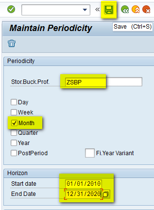
Figure 44
The storage bucket profile
Time Bucket Profile
The time bucket profile is used to define the time buckets that are used for planning the data and the sequence in which the time buckets appear. This is also known as the planning bucket profile.
To define the time bucket profile, execute transaction code /SAPAPO/TR30. In the initial screen that appears (Figure 45), enter a name for the time bucket profile (e.g., Z24MNTH) and short text (e.g., 24 Monthly Buckets). In the table in the Time Buckets Prof. Details section, enter 24 in the Number Field and M in the Display periodicity field. After you press Enter, the second row with Basic periodicity as M is automatically populated. Click the save icon to save your entries. This action completes the creation of time bucket profile.
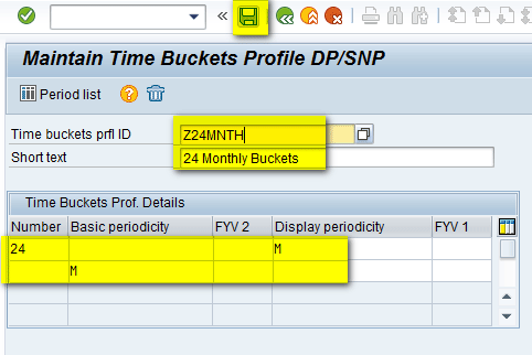
Figure 45
The time bucket profile
Master Planning Object Structure
A master planning object structure (MPOS) contains plannable characteristics for use in planning. To create an MPOS, execute transaction /SAPAPO/MSDP_ADMIN. The screen that appears (Figure 46) loads the default planning areas. To create a new MPOS, click the Planning Areas button and select Plng Object Structures (planning object structures) from the drop-down list of options shown in Figure 46.

Figure 46
Administration of DP
In the next screen (Figure 47), the system loads the MPOS. To create a new MPOS, right-click Plng Object Structures > Create Planning Object Structure.

Figure 47
Create an MPOS
In the pop-up screen that appears (Figure 48), enter a name for the MPOS (e.g., ZCBF_MP) in the Master Planning Obj. field and click the enter icon.
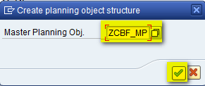
Figure 48
Enter the MPOS name
In the next screen (Figure 49), enter a short text description for the new MPOS (e.g., ZCBF - Master Planning Object Structure). Select the Charstc-Based Forecasting check box. This automatically brings the standard characteristics that are used in CBF on the right column (APO product, CBF profile, Char.-Based Fcst:Row and CBF Table) as shown in Figure 49.
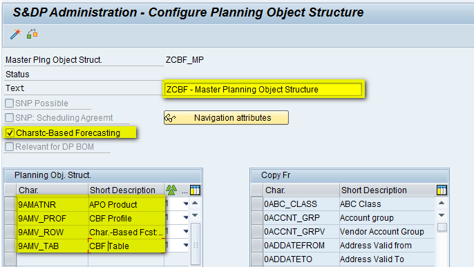
Figure 49
Enter a short text description for the MPOS
You also want to have a location characteristic in the MPOS, so select the 9ALOCNO Char. in the right column and move it to the left side as shown in Figure 50.
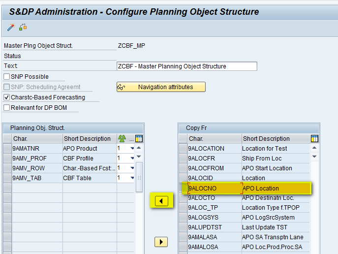
Figure 50
Move the location characteristic
Now the location characteristic is available in the left column as shown in Figure 51.

Figure 51
Location characteristic moved to the left column
After adding the required characteristics to the MPOS, activate the MPOS by clicking the activate icon (shown at the top of Figure 50). After you click the activate icon, the system internally checks and generates the required tables. On successful activation, a pop-up screen displays showing activation was successful as shown in Figure 52. Click the green checkmark to exit from the logs message.
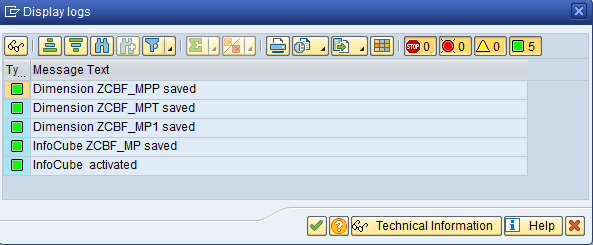
Figure 52
MPOS activation logs
Now the MPOS has been successfully activated with a green status as shown in Figure 53.
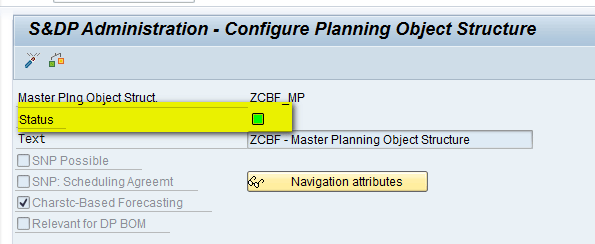
Figure 53
MPOS activated
Planning Area
A planning area is one of the most important areas in DP. It defines the area in which most of the planning activities take place. It groups together both characteristics and key figures under a single domain.
To create a planning area, execute transaction /SAPAPO/MSDP_ADMIN. The screen that appears (Figure 54) loads the default planning areas. To create a new planning area, right-click the Planning Areas > Create Planning Area.
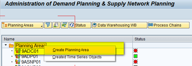
Figure 54
Create the planning area
In the pop-up screen that appears (Figure 55), enter the name of the Planning Area (e.g., ZCBFPA), the MPOS that was created (e.g., ZCBF_MP), the storage bucket profile that was created (e.g., ZSBP), and Unit of Meas. (e.g., EA). Click the enter icon (the green checkmark).
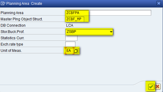
Figure 55
Create the parameters for the planning area
In the next screen (Figure 56), click the Key Figs tab, select the Forecast key figure, and move it from the right side to left side (the Planning Area is still not active, so the status is red).
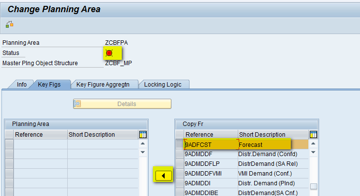
Figure 56
Select a key figure
Now the forecast key figure is available in the left column as shown in Figure 57.

Figure 57
Forecast key figure is available in the left column
After adding the required key figures, click the save icon to save the planning area as shown in Figure 58.

Figure 58
Save the planning area
The planning area is now created, but it is still not active. To activate the planning area, first you need to create characteristic combinations in MPOS. However, before that you need to complete CBF-related configurations.
Step 3. Configure Elements of the CBF Feature
In this section, I explain how to create a CBF table and configure a CBF profile. I also explain how to link the CBF profile to the CBF table.
CBF Table
To create a CBF table, execute transaction /SAPAPO/IPM01. In the initial screen, select CBF Table and enter a name (e.g., CBF_TAB) as shown in Figure 59. Click the Create button.
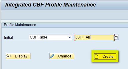
Figure 59
Create a CBF table
In the next screen, enter a short description of the CBF table (e.g., CBF Table). In the Struct tab, add the three characteristics defined above (COLORS, ENGINE, and WHEELS) as shown in Figure 60.
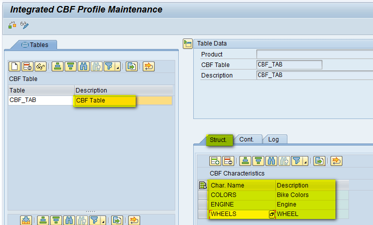
Figure 60
Assign characteristics to the CBF table
Now click the Cont. tab and create different combinations of the characteristics that are used for planning of the product (Bike in my example) by clicking the add icon as shown in Figure 61.
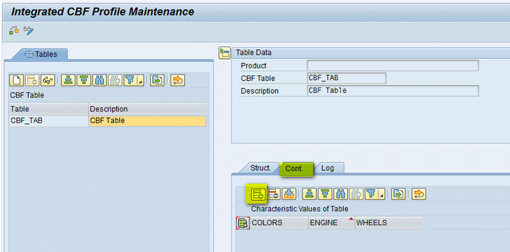
Figure 61
Click the add icon
After clicking the add icon, you can add different combinations of characteristics (i.e., different combinations are based on requirements for which you want to forecast) as shown in Figure 62. For my example, you create eight different combinations based on characteristic values.

Figure 62
Create combinations of characteristics
Once different combinations of the characteristics are defined, click the save icon (Figure 62).
CBF Profile and Linkage to CBF Table
To create a CBF profile, execute transaction /SAPAPO/IPM01. In the initial screen (Figure 63), select Product and enter the name of the product that you want to use for CBF (e.g., Bike-A). Click the Change button.
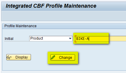
Figure 63
Enter the name of the product to use for CBF
In the next screen (Figure 64), click the create icon to create the CBF profile.

Figure 64
Create a CBF profile
In the same screen, enter the name of the CBF profile (e.g., CBF Profile) and select the check box in the Act (activate) column to activate the profile as shown in Figure 65.
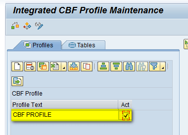
Figure 65
Activate the CBF profile
In the same screen, assign the CBF Table that you just created (CBF_TAB) to the profile by selecting the table and clicking the assignment icon as shown in Figure 66.
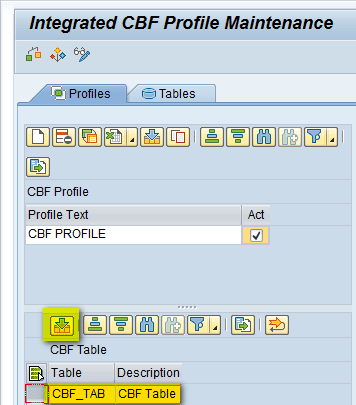
Figure 66
Assign the CBF table to the profile
After you assign the CBF table to the profile, all the characteristic combinations created in the CBF table automatically appear in the next screen (Figure 67). You can view them under the Charact. values combinatn/key column. Mark the required combinations that are relevant for planning by selecting the check boxes in the Relevant column.

Figure 67
CBF combinations assigned to the CBF profile
Click the save icon to save your entries as shown in Figure 68.

Figure 68
Save the CBF profile
Step 4. Configure DP
In this section, I explain the steps needed to configure DP.
Create the CVC
To create the CVC, execute transaction /SAPAPO/MC62 and in the screen (Figure 69) enter the name of the MPOS (e.g., ZCBF_MP) in the Master Planning Object Structure field. Click the Create Characteristic Combinations button.
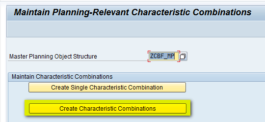
Figure 69
Create a CVC
In the next screen (Figure 70), select the Create Manually radio button and also select the Adjust Time Series Objects and Results Log check boxes. Click the execute icon.

Figure 70
The initial screen for creating the CVC
In the next screen (Figure 71), click the add icon.
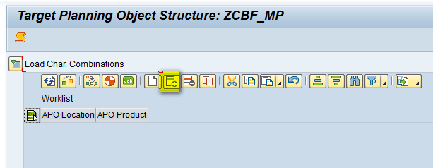
Figure 71
Add the CVC
In the next screen (Figure 72), enter the names of the location and the product created (e.g., PLANT1 and Bike-A) and click the Generate combinations button.
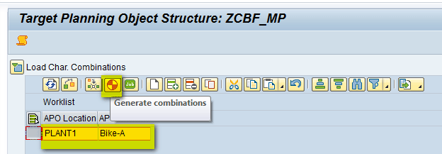
Figure 72
Generate combinations
The pop-up screen that appears displays a message that the MPOS is not used in any of the planning areas as shown in Figure 73. Click the green checkmark icon. You can ignore this as it’s just an information message and you link the planning area to the MPOS after you activate the planning area.
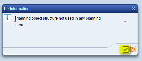
Figure 73
The pop-up message
Then, you can see the new characteristic combination created and a message appears at the bottom of screen showing that the planning object has been successfully created (Figure 74).
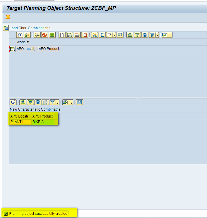
Figure 74
CVC created successfully
Display the CVC
To display the characteristic value combinations (CVC), execute transaction /SAPAPO/MC62 and in the screen that appears, enter name of the MPOS (e.g., ZCBF_MP). Click the Display Characteristic Combinations button (Figure 75).

Figure 75
Click the Display Characteristic Combinations button
In the next screen, click the execute icon (Figure 76).

Figure 76
The initial screen for displaying the CVC
The next screen (Figure 77) shows the list of CVCs. Note the CBF Profile and CBF Table columns are automatically populated based on the number assigned internally by the system. Also the number of rows (8 in my example) is due to eight combinations of characteristics that were created while creating the CBF table.
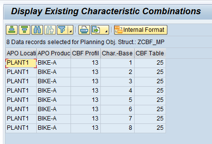
Figure 77
The CVC list
Create Time Series Objects
To activate the planning area, execute transaction /SAPAPO/MSDP_ADMIN. In the screen that appears (Figure 78), select the planning area that needs to be activated (e.g., ZCBFPA). Right-click it and select Create Time Series Objects. Note the status of the planning area as of now is Inactive as shown by the red status icon.
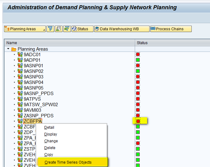
Figure 78
Create time series objects
In the pop-up screen that appears, enter the planning version (e.g., 000) and start and end dates of the time period for which the planning area needs to have time series created (e.g., 01/01/2010 to 12/31/2020). Note that this time range is the same as what was defined while creating the storage bucket profile. Click the execute icon (Figure 79).
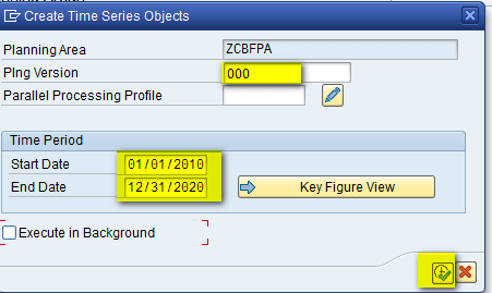
Figure 79
Create the parameters for the time series objects
The planning area is now successfully initialized and the status color changes to green, indicating that activation is successful (Figure 80).
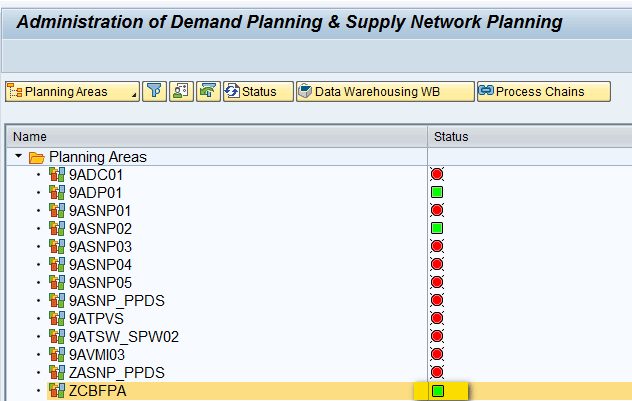
Figure 80
Planning area activation
Set Up a Planning Book and Data View
A planning book is constructed on the information or a subset of information maintained in the planning area. In the planning book, you select the characteristics and key figures that are required by demand planners to complete their tasks. The planning book determines the outline and layout of the interactive planning screen or book.
To create the planning book, execute transaction /SAPAPO/SDP8B. In the screen that appears (Figure 81), enter the name of the planning book (e.g., ZCBFPB) and click the Create button.
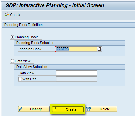
Figure 81
Create the planning book
In Figure 82, enter the Planning Book name (e.g., Planning Book – CBF), select the planning area on which planning book will be based (e.g., ZCBFPA), and click the Continue button. You can also select the different check boxes, such as Promotion and Univariate Forecast, as your business requirements.
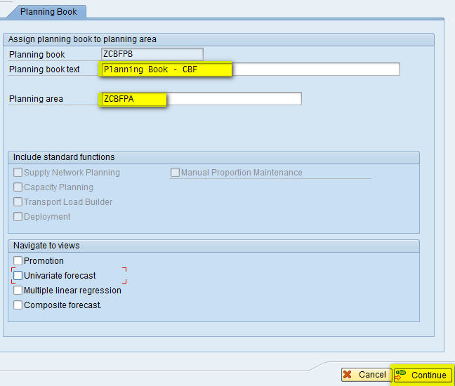
Figure 82
The initial screen for creating a planning book
In the next screen (Figure 83), assign the key figure from the planning area to the planning book. In this screen, you move the Forecast key figure from the Planning Area to the Planning Book by selecting the key figure and clicking the add icon.
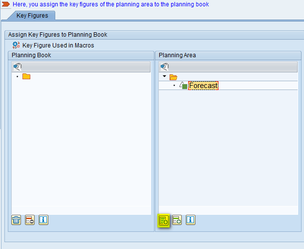
Figure 83
Assign a key figure to the Planning Book
Now the key figure is assigned to the Planning Book as shown in Figure 84. Click the Continue button.
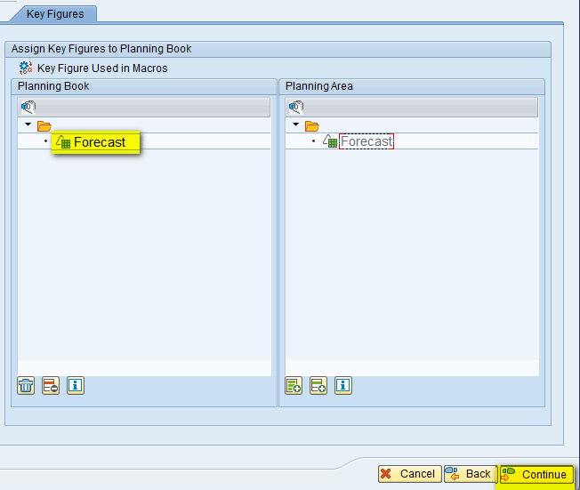
Figure 84
Key figure assigned
In the next screen (Figure 85), assign the characteristic from the Planning Area to the Planning Book. Move the APO Location and APO Product from the Planning Area to the Planning Book section by selecting the characteristic and clicking the add icon.
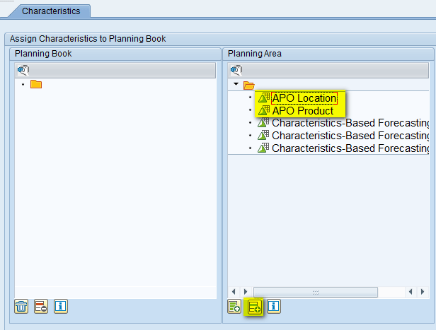
Figure 85
Assign a characteristic to the Planning Book
Now the characteristics are assigned to the Planning Book as shown in Figure 86. Click the Continue button.
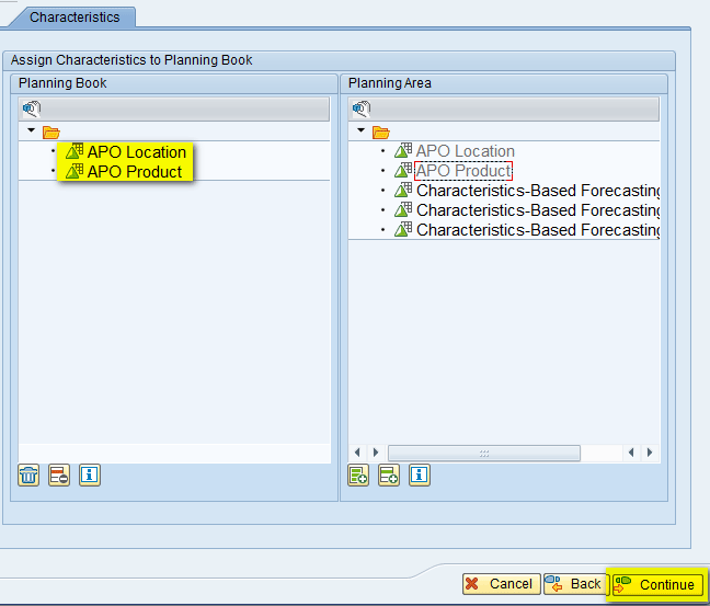
Figure 86
Characteristics assigned
In the next screen (Figure 87), enter the name of Data View (e.g., ZCBFDV) and a description in the Data View Descr. Field (e.g., CBF – Data View). Enter names in the TB Profile ID (Future) and TB Profile ID (Past) fields (e.g., Z24MNTH). Now click the Continue button.
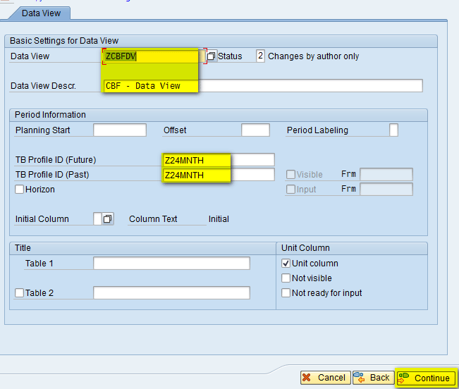
Figure 87
Populate fields for the data view
In the next screen (Figure 88), assign the key figure from the Planning Book to the Data View. In this screen, you move the Forecast key figure from the Planning Book to the Data View by selecting the key figure and clicking the add icon.
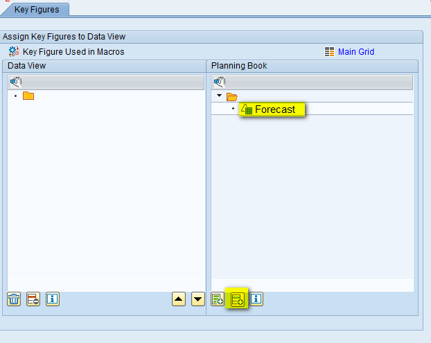
Figure 88
Assign the key figure to the data view
Now the key figure is assigned to the data view as shown in Figure 89. Click the Complete button.

Figure 89
Key figure assigned to the data view
A pop-up screen displays a message that asks for confirmation to complete the planning book or data view creation process (Figure 90). Click the Yes button.
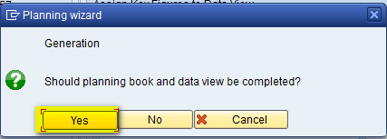
Figure 90
Confirm that you want to complete the creation of the planning book or data view
This completes the process of creation of the planning book/data view
Add Forecast Values
To see the new planning book or data view that you just created and to forecast values against different characteristic values, execute transaction code /SAPAPO/SDP94. In the screen that appears (Figure 91), select the planning book or data view created (e.g., ZCBFPB/ZCBF/DV) and double-click it.
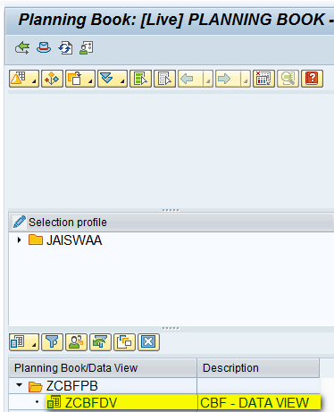
Figure 91
Select the planning book or data view
In the right side of the next screen (Figure 92), you can view the planning book or data view. Currently, it is empty as no values have been entered.

Figure 92
View the planning book or data view
To load the characteristics, click the selection icon shown in Figure 93.

Figure 93
The planning book selection option
In the pop-up screen that appears (Figure 94), click the Show field and select APO Product from the list of options. In the field beside APO Location select a parameter (e.g., PLANT1) and click the Continue button. (Note: The APO Planning Version = 000 is automatically populated).
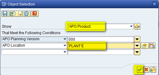
Figure 94
Loading selections
The APO Product assigned to Location (PLANT1) is now loaded (Figure 95). Select it and double-click the row to load it in the planning book on right side of the screen.
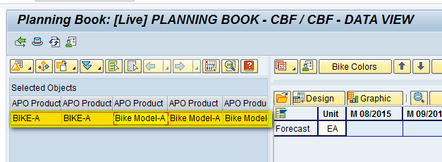
Figure 95
Load the characteristics to the planning book
In the right side of the next screen, the values are loaded. Because no values have been entered now, all cells are blank (empty) as shown in Figure 96. Also at the top you can see all the three characteristics (Bike Colors, Engine, and Wheel are present at the Total level).

Figure 96
Data loaded to the planning book
To drill down at the detailed level, click the characteristic (e.g., the Bike Colors button) and click Details (all) as shown in Figure 97.

Figure 97
Drill down on colors
In the next screen (Figure 98), you can see all the values defined for the characteristic (e.g., Color).

Figure 98
Drilled-down level
You can follow these steps for other the two other characteristics also (e.g., Engine and WHEEL) and the planning book is presented at a detailed level as shown in Figure 99.
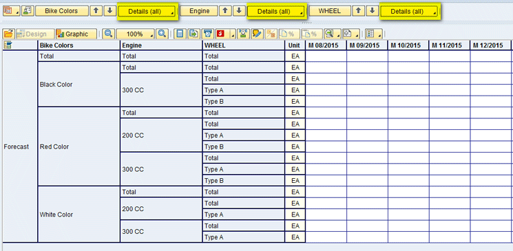
Figure 99
Detailed level of the planning book
You can enter forecast values for different combinations as shown in Figure 100.
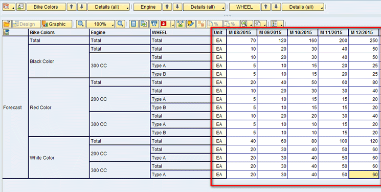
Figure 100
Forecast values entered
After you enter the forecast values, save the values by clicking the save icon in Figure 101.

Figure 101
Save the data
Step 5. Configure a Consumption Group
Consumption groups are used along with descriptive characteristics to release the forecast at a more detailed level than the product location. For example, there could be a scenario in which you may want to create forecasts for specific bike colors and then consume this forecast when the customer places an order. You can use a consumption group in such a scenario. The main advantage here is that it provides you with a lot of flexibility when doing planning.
Create a Consumption Group
To go to Consumption Group, execute transaction code SPRO and follow IMG menu path > Advanced Planning and Optimization > Supply Chain Planning > Demand Planning (DP) > Basic Settings > Consumption > Maintain Consumption Group. Click the execute icon beside Maintain Consumption Group.
In the initial screen that appears (Figure 102), select the Hdr data folder. In the Consumption Group section, enter a name of the Consumption Group (e.g., CBF_CG), a Description (e.g., CBF Consumption Group), and a Planning Area name (e.g., ZCBFPA).

Figure 102
The consumption group header
Now select the Details folder and click the DP Charac. Assignment tab. Select all the characteristics defined (e.g., Bike Colors, Engine, and Wheel) and move them to the left by selecting the arrow as shown in Figure 103.
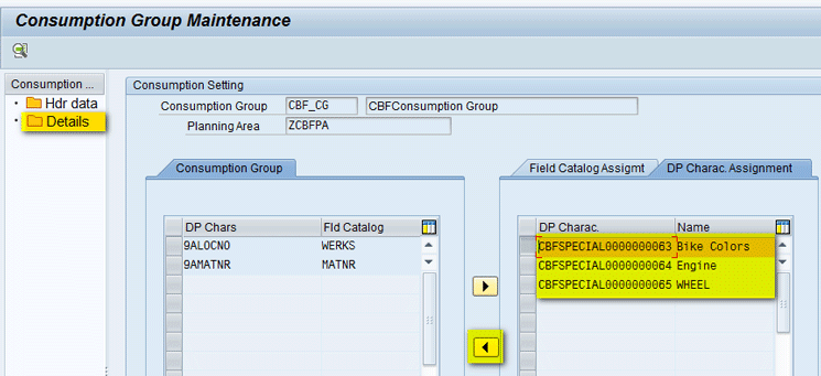
Figure 103
Consumption group details
After all the characteristics are moved, they appear on the left side under Consumption Group (Figure 104). Click the save icon to save the defined consumption group.
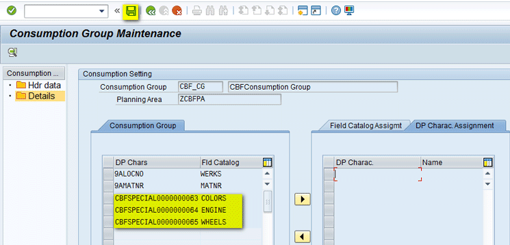
Figure 104
Save the consumption group
Assign a Consumption Group to the Product Master
Now, you need to assign the consumption group to the product master. Execute transaction code /SAPAPO/MAT1. In the initial screen that appears (Figure 105), enter a name of the product (e.g., Bike-A) and select a name of the location (e.g., PLANT1) in the field to right of the Location radio button. Click the Change button.
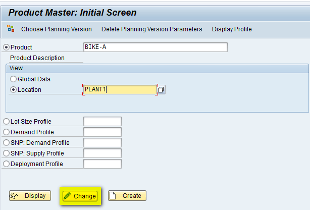
Figure 105
Change the product master
In the next screen, click the Demand tab and assign the consumption group created in above step (CBF_CG) as shown in Figure 106. Click the save icon to save the product.
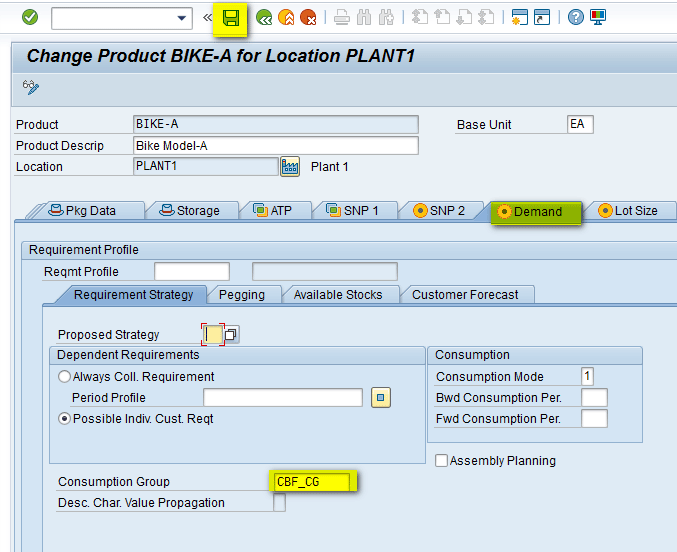
Figure 106
Assign the consumption group to the product master
Step 6. Release the CBF Demand
After the forecasting process is complete, you need to release the forecast from DP to supply network planning (SNP) or production planning-detailed scheduling (PP/DS) where it can be used for medium- to short-term planning and converting the forecast requirements to planned orders.
Release a Forecast from DP
To release the forecast, execute transaction code /SAPAPO/MC90. In the next screen (Figure 107), enter the Data Source parameters: Planning Area – ZCBFPA, Planning Version – 000, Key Figure – 9ADFCST [Forecast Key Figure]), Target parameters (e.g., Planning Version – 000, Category – FA, which stands for Forecast), Horizon for which forecast data would be released (e.g., Aug – Dec 2015), Planning Buckets Profile (e.g., Z24MNTH), Object Selectn (e.g., Product – Bike-A, Location – PLANT1), and the Consumption Group (e.g., CBF_CG). After you enter all the parameters, click the execute icon.
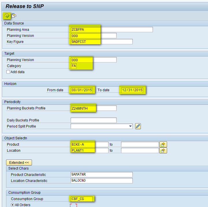
Figure 107
Release the forecast from demand planning
The next screen (Figure 108) displays the result logs. The logs indicate that the release is successful.
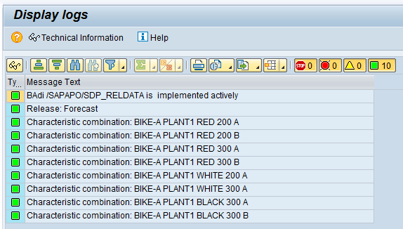
Figure 108
Forecast release logs
Validate a Forecast in the Product View
To see the released forecast, execute transaction code /SAPAPO/RRP3 (Product View). In the screen that appears (Figure 109) enter the parameters (e.g., Planning Version – 000, Product – Bike–A and Location – PLANT1) and press Enter.

Figure 109
Go to the product view
The next screen displays the forecast data as shown in Figure 110.
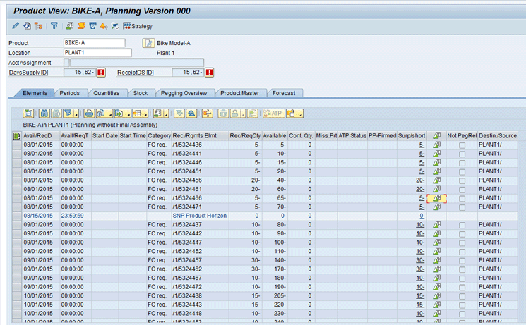
Figure 110
Product view output
Interpret the Results
To see the details of forecast, select the first row and click the value assignment icon as shown in Figure 111.
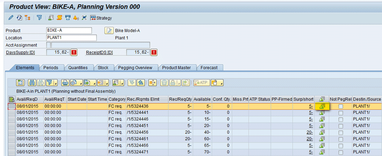
Figure 111
Value assignment in the product view
In the pop-up screen that appears (Figure 112), you can see that the forecast value of 5 in Aug-2015 from Figure 111 is assigned for the characteristic (Red color, 200 cc Engine, and Wheel type A). Click the Continue button.
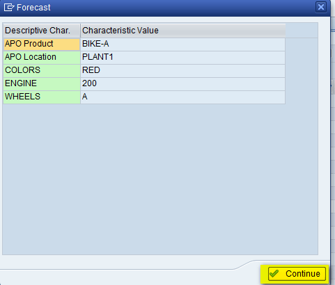
Figure 112
Characteristics details
If you compare the value that was maintained for the planning book (Figure 100), the value of 5 was maintained for Red Color, 200 cc Engine, and Wheel type A. So the same value is now released from DP. This shows that instead of showing the forecast values at the product-location level (e.g., Bike-A, PLANT1), through the use of CBF in DP, you can release the forecast at a more detailed level.
Similarly in the Forecast tab, you can see details of forecast that was released and the corresponding characteristics to which it is assigned, as shown in Figure 113.
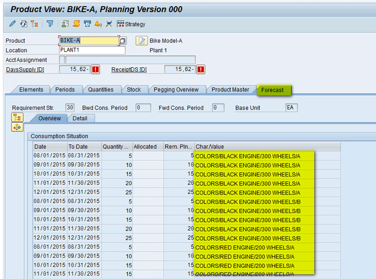
Figure 113
Forecast in the product view
Alok Jaiswal
Alok Jaiswal is a consultant at Infosys Limited.
He has more than six years of experience in IT and ERP consulting and in supply chain management (SCM). He has worked on various SAP Advanced Planning and Optimization (APO) modules such as Demand Planning (DP), Production Planning/Detailed Scheduling (PP/DS), Supply Network Planning (SNP), and Core Interface (CIF) at various stages of the project life cycle.
He is also an APICS-certified CSCP (Certified Supply Chain Planner) consultant, with exposure in functional areas of demand planning, lean management, value stream mapping, and inventory management across manufacturing, healthcare, and textile sectors.
If you have comments about this article or publication, or would like to submit an article idea, please contact the editor.


