Learn how to integrate SAP Manufacturing Integration and Intelligence (SAP MII) with manufacturing automation systems using SAP Plant Connectivity (PCo) by query and notification agents for real-time process visibility in manufacturing operations. Understand the use cases of process event management by connecting to different types of manufacturing automation source systems and SAP MII as the destination system.
Key Concept
SAP Plant Connectivity (PCo) is an add-on component to SAP Manufacturing Integration and Intelligence (SAP MII) that provides bidirectional connectivity with a manufacturing automation control system such as supervisory control and data acquisition (SCADA), distributed control system (DCS), or Plant Data Historian.
Note
Prerequisites for being able to go through the steps in this article are knowledge of shop floor automation systems and SAP MII.
Why Do You Need to Integrate with Manufacturing Automation Systems?
A manufacturing shop floor consists of numerous machines and devices that generate huge amounts of process data continuously. It is critical to ensure that the data is analyzed and acted upon in real time to ensure smooth operations and quick decisions in case of deviations.
As explained in Figure 1, manufacturing IT consists of five levels of systems as defined by the Instrumentation System and Automation Society (ISA).
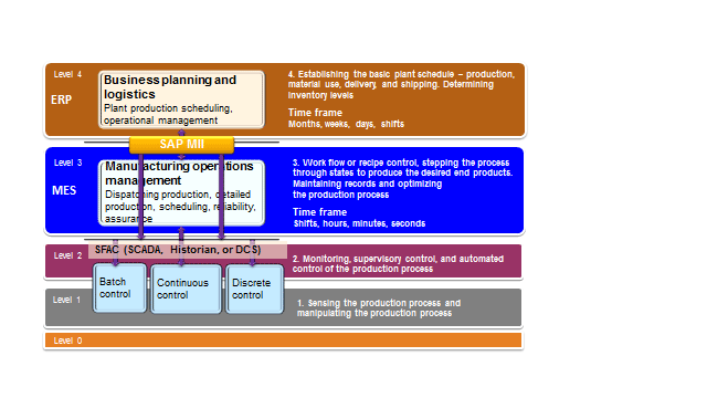
Figure 1
Level 0 to level 4 in manufacturing and SAP MII positioning
Level 0 is for the physical machine layer used in manufacturing plants. Level 1 is for the sensors and programmable logic controllers (PLCs) that collect the data points in time-series format from the machines in real time. Level 2 provides the control systems and Plant Data Historian to provide the process control and time-series data storage and monitoring. A manufacturing execution system (MES) provides the applications to manage the production process, recipe management, shift planning, and control that are considered level 3. ERP is the planning and logistics execution system for the enterprise that is considered to be level 4.
The data generated from level 0 to level 4 varies by time frame. For example, data in SCADA or Plant Data Historian are process parameter data points in milliseconds, seconds, or minute intervals, whereas the data in an MES and ERP has broader time frames, such as hours, minutes for the execution planning, and weeks, months, quarters, or years for enterprise logistics planning.
Varying data granularity at different levels and applications from multiple heterogeneous platforms always present a challenge for integrating systems in real time in a manufacturing organization, keeping different levels in mind. This leads to a lack of visibility and a delay in decision making, which ultimately affects the product quality, profitability, and customer satisfaction.
Consider this example — the machines on the shop floor may have various levels of automation and can experience mechanical, electrical, or process faults during their operations. This information might lead to deviation or temporary stoppage of production operations.
Although the level 2 automation control systems capture the machine downtime information, if you lack real-time connectivity with the automation systems from the enterprise planning systems, the information may not flow to the execution and planning systems quickly. That may lead to the delay of re-planning or corrective actions, thereby affecting the production run schedule and key performance indicators (KPIs).
If the level 2 automation control systems are connected in real time with the level 3 and level 4 systems, subsequent follow-up actions for maintenance and production can be triggered automatically. That enables corrective actions in real time, such as triggering plant maintenance notification, sending alerts to concerned persons, and rescheduling of the production activity as required.
Architecture Overview to Integrate with an Automation System in Real Time to Monitor Equipment Downtime
SAP MII acts as the integration and composition platform for the manufacturing execution domain. By providing various types of connectors to integrate with level 2 automation control systems, such as SCADA and Plant Data Historian, as well as level 3 MES and level 4 ERP systems through standard connectors, SAP MII can be used to integrate the manufacturing plant applications with the enterprise planning and logistics applications. It also can provide intelligent reports and visualization of the process data.
SAP Plant Connectivity (PCo) is based on Microsoft .Net Framework 4.0. It provides the following connectors as source systems in version 15.0:
• OPC Data Access (OPC DA)
• OPC Historical Data Access (OPC HDA)
• OPC Alarms & Events (OPC A&E)
• OPC Unified Architecture (OPC UA)
• Object linking and embedding (OLE) Database (OLE DB)
• Open Database Connectivity (ODBC)
• GE Fanuc Proficy Historian (iHistorian)
• OSIsoft PI (PI)
• TCP/IP Socket
• IP21 (Aspentech InfoPlus 21)
• Citect (Plant Historian and SCADA applications from Schneider Electric)
• File Monitor (File System)
PCo provides query and notification mechanisms to retrieve data and publish-subscribe scenarios. A query mechanism can be used with tag queries, PCo queries, or Structured Query Language (SQL) queries from SAP MII to retrieve the data from the underlying systems on an on-demand basis. (Tag queries are used to query tag values in a source system.) A notification feature in PCo enables you to subscribe to one or more tags in the source system. If a tag value changes and satisfies a certain condition, PCo sends a notification message to the target system.
PCo supports the following systems as its destination systems to send the data as notifications:
• SAP MII
• SAP Manufacturing Execution (SAP ME)
• Business Suite system, for example, SAP ERP or Extended Warehouse Management (EWM)
• Sybase Event Stream Processor (Sybase ESP)
• SAP HANA database
• Microsoft SQL Server
Although it is possible to send notifications from PCo directly to systems such as Business Suite, Sybase ESP (Event Stream Processor), or SAP HANA, it may not always be meaningful to send the raw tag information to business systems without the actual context to it, such as the corresponding machine, parameters, or process information. Because SAP MII is an integration and composition platform, it is easy to develop the logic to attach the business context to the data from PCo and consolidate it to send to other systems for further processing.
Figure 2 provides the architecture overview of the integration scenario between manufacturing automation systems in level 2 and SAP ERP in level 4 using SAP MII.

Figure 2
Architecture of manufacturing automation systems integration with SAP ERP using SAP MII
Connecting to the Machine Data Sources
To get the real-time information from level 2 automation control systems, the first step is to connect to those systems through the interfaces provided in these level 2 automation control systems. The data can then be retrieved either by query from SAP MII in an ad hoc basis or via notifications sent from PCo to SAP MII, on a change of tag values. PCo provides the direct connectivity to the automation control systems with SAP MII.
In this example I explore how to connect to an automation control system to get machine downtime information. To connect to the automation control system (e.g., a Plant Data Historian), first you need to configure a source system in PCo. PCo can connect to SCADA and Plant Data Historian systems through an OPC server or directly to the source system for which the connector is provided.
Assume that the values for certain parameters of a machine signify the downtime of that machine. These values are available as tags in a Plant Data Historian that provides an OPC Data Access (DA) interface. In this example I use an OPC DA, HDA (Historical Data Access), and UA (Unified Architecture) simulators as the Plant Data Historian simulator as the level 2 automation systems simulators. Usually the OPC server is available in the SCADA or Plant Data Historian or needs to be installed separately.
PCo is a Microsoft Windows executable program. I recommend that you install it in the same Windows server where the source system is installed to avoid complex firewall and Distributed Component Object Model (DCOM) security configurations.
After you open the PCo management console, click the new source system icon to open a dialog box from which the type of source system needs to be selected. For this example, select the OPC DA agent as the OPC simulator provides the OPC DA connector to get the current tag values. The source agent type should be selected based on the type of the source system connector type (e.g., while connecting to an OSI PI Historian system, you need to select the PI agent).
Specify a name of the source system agent and an option description for the same and click the OK button. The source system is now created. Selecting the source system just created displays the connectivity details for this source system on the right-side pane, where the server details of the source system needs to be selected.
Figure 3 shows the selection of a new source system.
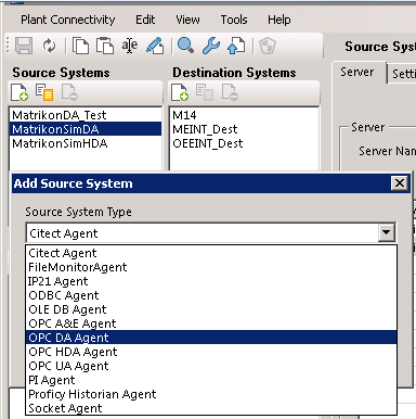
Figure 3
New source system in PCo

Figure 4
Source system configuration in PCo
Note
PCo can be used to connect to files, databases, and TCP/IP sockets as well by using the FileMonitor, ODBC or OLE DB, and Socket agents, respectively. FileMonitor agent is useful when you want to read or write a file from the file system and ODBC for querying from a local database using a system database source name (DSN). A socket agent is required to connect to a system through serial ports (sockets). Examples are reading from comma-separated value (CSV) or text files generated by automation systems where OPC or supported interfaces are not provided using FileMonitor agent, accessing Microsoft Access or Excel files as databases using OLE DB and ODBC agents, or connecting to a label printer or weighing scale through TCP/IP sockets using socket agent.
For a FileMonitor agent, the file path in a local or network folder needs to be provided from where the file should be read, and if required, the destination folder where you want to move the file. For the Socket agent, you need to specify the TCP/IP address, port, and the terminator and length of each message. The socket agent can use both IPv4 and IPv6 sockets.
Figures56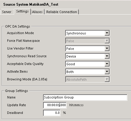
Figure 5
Settings configuration for OPC DA source system
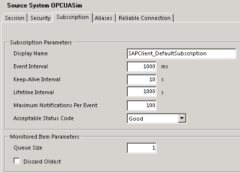
Figure 6
Subscription configuration for OPC UA source system
This is important in controlling in what granularity or frequency the data should be collected from the source system. However, it does not necessarily mean that the data will be sent to the target system as notifications in the same frequency at which it is read from the source system. You’ll see how to control that in the notification configuration in the next section. This will be useful when getting data for consolidation such as a production count from the can counter (used to count the cans coming out of a production line).
Capturing the Real-Time Data
After you connect to the source system, you need to configure the agents, destination system, and notifications to capture the real-time data and process it to derive process intelligence. This section shows how to configure the PCo agents.
Configuring the PCo Agent
After the source system is configured, the next step is to configure the data acquisition and notification mechanism. To do that, first an agent instance needs to be configured for a source system in PCo. An agent is a logical client through which the tag data from the source system can be queried or subscribed.
To create a new agent instance, click the new icon in the Agent Instances section or select New > Agent Instance from the Plant Connectivity menu. In the pop-up dialog screen, select the source system for which the agent is being configured and specify a name and description (optional) as shown in Figure 7.
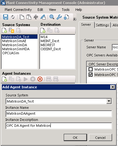
Figure 7
Agent configuration
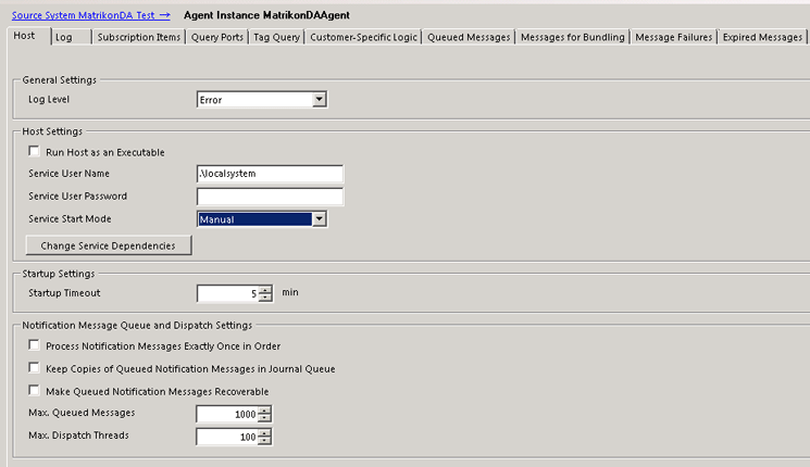
Figure 8
Host configuration in an agent
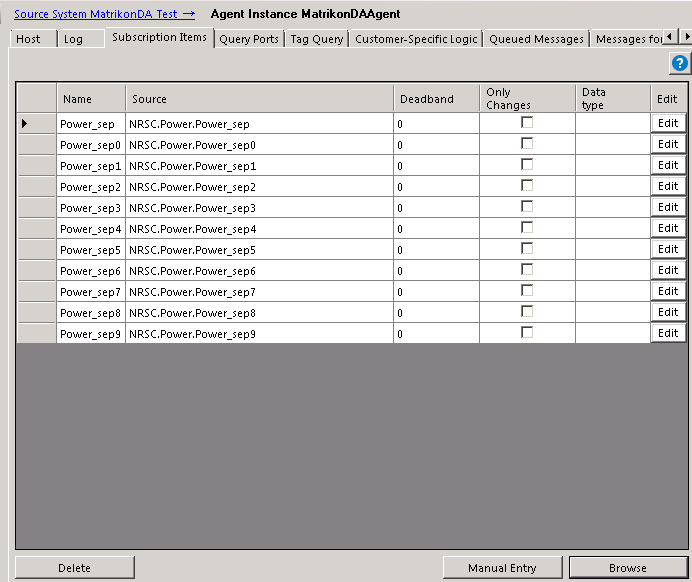
Figure 9
Subscription items configuration

Figure 10
Query port configuration for SAP MII (PCo)

Figure 11
WebSocket configuration
Configuring the Destination System
After the source system and agent are configured in PCo to connect to the data source, a destination system needs to be configured. It is required only for notification scenarios to send the notification messages on a change of tag values. It is not required for ad hoc queries from SAP MII by PCo query or tag query.
Different types of destinations can be configured in PCo to send the notification messages such as SAP MII, SAP ABAP WebAS (RFC), Sybase ESP, or any applications having Representational State Transfer (REST) or Simple Object Access Protocol (SOAP) web service, ODATA, or ODBC interfaces. In most cases the SAP MII destination is used to capture the notification message sent from PCo and process it according to business context. This is important as the context information such as production line and order number usually cannot be specified in the notification message sent from PCo. The message may contain only the tag information.
In SAP MII it is easier to add the business context information with the data sent in a notification message using the information configured in Plant Information Catalog (PIC) or by querying the information from a custom table and SAP ERP where the tag to production line or work center relationship are maintained. For the machine downtime scenario, you create a destination of type SAP MII Destination to send notifications on certain conditions to SAP MII to determine the machine or work center that is down, as shown in Figure 12.
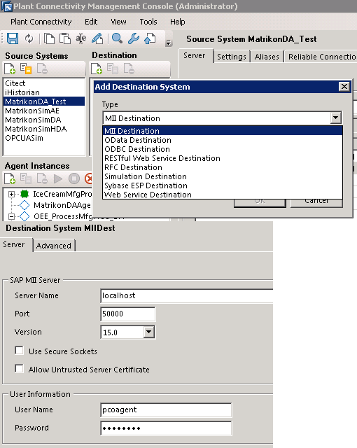
Figure 12
Destination configuration in PCo
Configuring the Notification for Processing Events
When the value in the tag in the automation system changes due to the change of the physical parameters in the machines, it requires some action to be taken. For example, when the speed of a machine falls below a certain value, it can be considered as a downtime or machine fault that probably needs some maintenance. Therefore, if a tag in the Plant Data Historian is maintained for recording the machine power consumption from the sensor, whenever it falls below a certain limit for at least one minute, an alert and plant maintenance notification should be triggered.
To enable this scenario, a notification needs to be created for the PCo agent created earlier to monitor the specific tag in the source Plant Data Historian system and trigger a notification message when the tag value crosses the threshold limit. Notification can be created for all types of OPC-based sources systems, OSIPI, Proficy Historian (iHistorian), and Socket agent.
For an OPC DA type of source system, the source system itself evaluates the condition specified in PCo sending the signal to PCo to trigger the notification. For all other types of source systems, PCo itself evaluates the triggering condition continuously based on the update rate or event interval in the source system settings configuration to generate the notification.
To create a notification, select the agent created earlier and click the create notification icon to create a new notification. Specify a name and an optional description for the notification as shown in Figure 13. Multiple notifications can be created for an agent for different conditions.
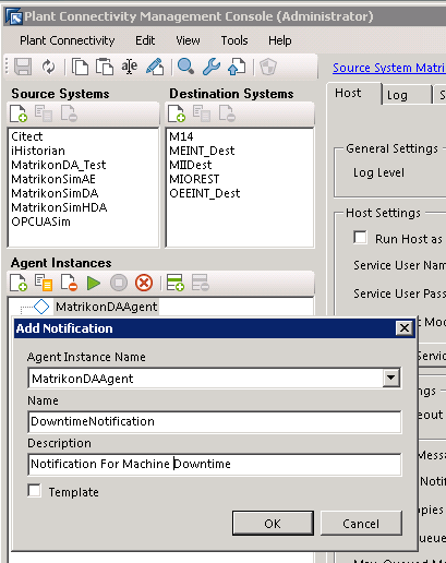
Figure 13
Notification configuration for an agent
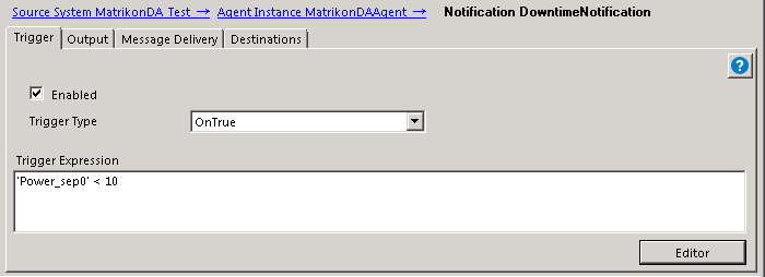
Figure 14
Trigger expression in notification
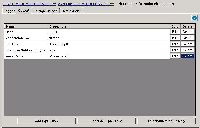
Figure 15
Output configuration of notification

Figure 16
Trigger and output configuration of notification
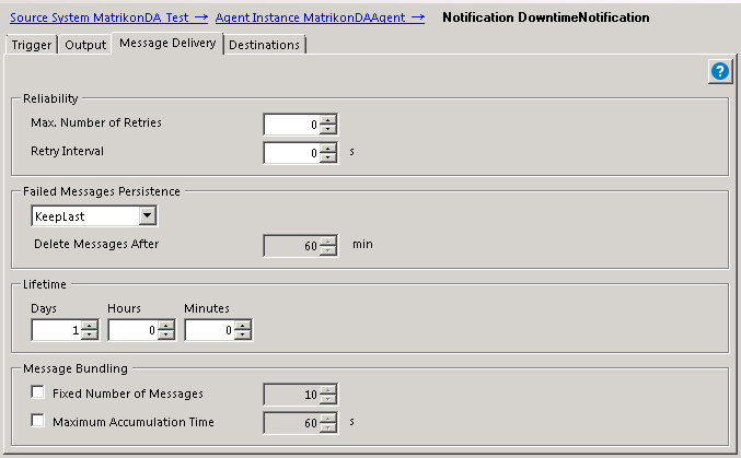
Figure 17
Message delivery configuration for notification
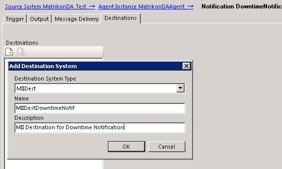
Figure 18
Notification destination configuration
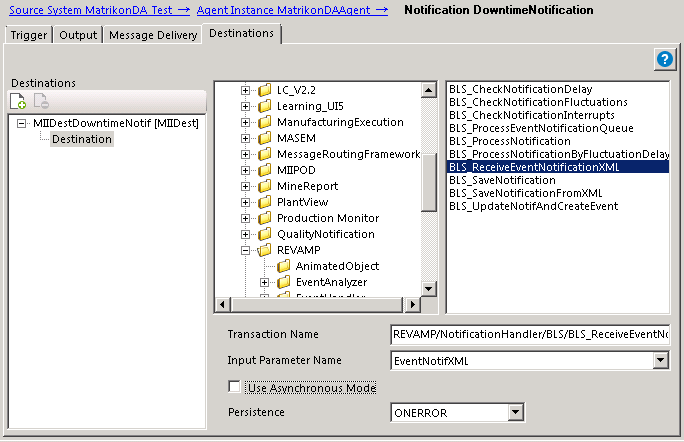
Figure 19
Destination transaction configuration for SAP MII Destination type
Apply a Business Rule to Determine the Event
In the BLS transaction in SAP MII that is used as the destination for the PCo notification, develop the logic to receive and process the notification XML from PCo to determine the machine downtime. To keep it simple, consider the machine is down if there is a notification message received with DowntimeNotificationType as true or 1, which checks the condition of the machine downtime in the PCo notification and sets true or false as applicable.
Whenever there is a change value of the Power_sep0 tag, PCo sends a notification message to SAP MII as the triggering condition is selected always with no triggering expression. This is because you need the notifications when both the downtime starts and ends as well (i.e., the power value of both less than 10 [for downtime start] and greater than 10 [for downtime end]). The notification XML message sent by PCo to the destination system is based on the output configuration of the notification (Figure 20).
  <?xml version="1.0" encoding="UTF-8"?>
- <NotificationMessage>
   - <Header>
        <Name>TestNotificationMessage</Name>
      - <Description>
           <![CDATA[Test Message]]>
        </Description>
        <Destination/>
        <CreatedDate>2015-01-13T03:21:33</CreatedDate>
        <ID>49bfddb6-6f26-44b0-a032-91c77943c6cb</ID>
        <Status>Created</Status>
     </Header>
   - <Body>
      - <Values>
         - <Plant timeStamp="0001-01-01T00:00:00" quality="None" type="xsd:string">
               <![CDATA[1000]]>
           </Plant>
        - <DowntimeNotificationType timeStamp="0001-01-01T00:00:00" quality="None" type="xsd:string">
             <![CDATA[1]]>
          </DowntimeNotificationType>
        - <PowerValue timeStamp="0001-01-01T00:00:00" quality="None" type="xsd:string">
             <![CDATA[9]]>
          </PowerValue>
        - <TagName timeStamp="0001-01-01T00:00:00" quality="None" type="xsd:string">
             <![CDATA[Power_sep0]]>
          </TagName>-<NotificationTime timeStamp="0001-01-01T00:00:00" quality="None" type="xsd:string">
              <![CDATA[2014-10-10T06:09:00]]>
          </NotificationTime>
       </Values>
     </Body>
    <Faults/>
</NotificationMessage>
Figure 20
Notification XML sample message
The elements and the values specified in the output configuration are present under the NotificationMessage > Body > Values path in the XML message. The processing transaction needs to parse the XML message to get the values from the corresponding elements in the above path. If required you can develop complex logic in the processing transaction to wait for a certain time to check if there is any reverse notification coming in within a very short interval. In that case, the original notification can be nullified as it signifies that the value has gone beyond the threshold limit only for a very short time and it may not be an actual downtime for the machine.
If message bundling is used, multiple NotificationMessage elements are added under a NotificationMessages element. You can add a repeat logic on the individual notification message in the processing transaction to determine the notification state.
Another important point is to determine the corresponding machine for the tag specified in the notification message. You can maintain a mapping between the machine (equipment ID) and tag from different automation systems in a database table or Manufacturing Data Object (MDO) in SAP MII. While you receive the notification message from PCo based on the Tag and Plant and the data source, you can query the corresponding equipment ID using the PCoQuery.
Note
You can also use Plant Information Catalog (PIC) for maintaining the relationship of the tags with the ERP objects, such as equipment and work center. PIC provides a framework in SAP MII to maintain the hierarchy of plant assets and map PM equipment and PP work center from SAP ERP and tag information from the PCo connector as properties.
The PIC also provides a SOAP web service to search by a tag name and retrieve the corresponding namespace and property details. You can use the Browse PIC service with the GetTagDetails method to retrieve the corresponding machine information from the tag name received in the notification message from PCo.
https://<server>:<port>/PlantInformationCatalogService/PlantInformationCatalogServiceBean?wsdl&mode=ws_policy
You need to pass the Tagname as maintained in PIC in SAP MII. This Tagname is the tag in PIC as Tag Alias property, in the web service request and not the actual tag name from the source system, if different. The web service response provides the list of properties for the tag which may contain the ERP asset details if already mapped.
Getting the Historical and Real-Time Status of the Machine
Once the machine downtime is determined from the notification messages from PCo, you may need to provide a monitoring and analytics dashboard to display the current status of the machine and its trend based on the tag values. Therefore, you must connect to the data source via PCo and query the tag to display the current status and trend values.
To query the data on ad hoc basis via PCo, you can use PCo query in SAP MII to query the current or historical values from a tag. To query the tag, first a connection needs to be created to the PCo server. Log in to SAP MII using the URL https://<host>:<port>/XMII/Menu.jsp and follow menu path Data Services > Data Servers to create a data server of type PCoConnector.
Click the Create button and select connector type PCoConnector. Specify a name and optional description. Next, provide a PCoManagement Service URL. This URL is in the form https://<host>:<port>/PCoManagement as shown in Figure 21. Note the host name should be the server hostname/IP where the PCo is running and the port is defined in Management Host setting in PCo as explained in an earlier section. If asked for authentication, provide an OS administrator user authentication for the server where PCo is installed.

Figure 21
PCo data server configuration in SAP MII

Figure 22
The PCo query template

Figure 23
PCo query template configuration
Note
You can use Universal Data Connector (UDC) and TagQuery while using SAP MII 12.1 or earlier versions as PCo connector and PCo query are not available there. UDC is the predecessor of PCo Connector. It works in almost the same way as PCo query except for a few advanced features. Note that for PCo connector the Query Port specified in PCo agent for SAP MII is used, whereas for UDC the port mentioned under SAP MII before 12.2 is used.
The application architecture for the SAP MII application is shown in Figure 24.

Figure 24
Architecture overview of SAP MII application for event handler and reporting
The dashboard is where you can display the images of the machines as maintained in the tag equipment mapping table and then display the current tag value and last event that occurred on the machine (Figure 25). You can display the current tag value by querying the tag using PCo query using Animated Object as shown in Figure 25 or by using WebSocket in SAPUI5-based user interfaces if used in SAP MII 15.0. The animated object needs to be created dynamically by BLS transaction based on the tag value as obtained by the PCoQuery. Using animated objects for current tag value display, you need to enable periodic refreshing of the image using a JavaScript function executing the BLS transaction by the Runner service to generate the animated object. With WebSocket the value and display change automatically whenever there is a change of the tag value at the source system.
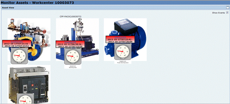
Figure 25
A sample dashboard for real-time display of events and status of machines
Note
You can use create an SAPUI5-based user interface to display the real-time status of machines using the Self-Service Composition Environment (SSCE) available in SAP MII 15.0. For that you need to map the tag in the Plant Information Catalog in SAP MII via the PCo connector you have configured. You use the tag from the PIC in the SSCE dashboard to display the tag value with real-time updates and also to customize it to display in different colors or icons dynamically based on the tag value.
Dipankar Saha
Dipankar is an IT architect working in IBM India. He has more than 12 years of experience in the IT industry and experience in implementing several SAP MII-based solutions globally. Dipankar is the coauthor of a book on SAP MII published in 2009. He is also an IBM-accredited IT architect and an SAP-certified associate enterprise architect.
You may contact the author at dipankar.saha@in.ibm.com.
If you have comments about this article or publication, or would like to submit an article idea, please contact the editor.


