Creating Solution Documentation Assistant Check Step Rules Using a Solution Manager Project
The Solution Documentation Assistant (SDA) uses rules to analyze managed systems and to generate technical and process documentation on how the systems are being used. One of the rule types is a transaction rule. Creating transaction rules in the rules database is easy, but if you need to create a lot of them, it can be quite tedious using the rules database editor. I show you how to make short work of creating a large number of transaction rules for use in your analysis projects using a Solution Manager implementation project.
Setup Process
Using a Solution Manager implementation project to create transaction rules requires that you actually have an implementation project.
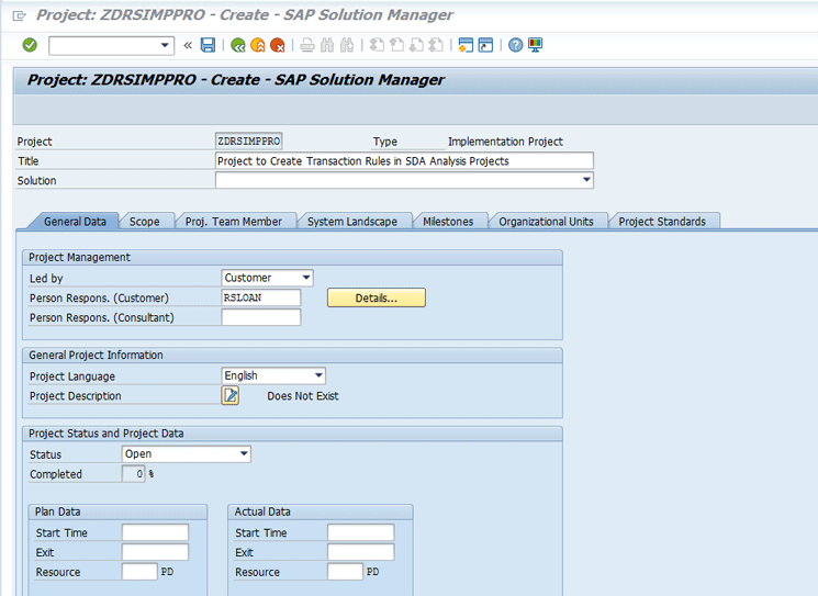
The first step is to use transaction SOLAR_PROJECT_ADMIN to create the implementation project. All you need is a project name, project title, project language, and a logical component for the system landscape. Figure 1 shows the SOLAR_PROJECT_ADMIN Create project screen with the name, title, and language parameters already filled in.
Click the System Landscape tab to enter one or more logical components. Solution Manager uses logical components to navigate the system landscape to access the managed systems.
Figure 2 shows the System Landscape tab with two logical components assigned. For this article, I focus on the ZECC_OMG logical component for the OMG landscape because it has a production system assigned to it.

After you create the project, the next step is to populate it with the transactions you wish to analyze in the managed system. Transaction code SOLAR01 opens the Business Blueprint view of Solution Manager projects. Execute transaction code SOLAR01 and choose the project you just created.
If this is the first time you’re using SOLAR01, a Project Selection pop-up screen appears. If you’ve used SOLAR01 previously, the last project accessed is automatically selected. Click the other project icon ![]() to open the Project Selection pop-up screen. Double-click your project to open it in the Business Blueprint maintenance screen. Figure 3 shows a project with a project step called Custom Trans for capturing the custom transactions I want to analyze in the managed system.
to open the Project Selection pop-up screen. Double-click your project to open it in the Business Blueprint maintenance screen. Figure 3 shows a project with a project step called Custom Trans for capturing the custom transactions I want to analyze in the managed system.
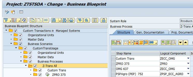
The next step is to add the transaction codes you want to analyze. Select the Custom Trans process step and then click the Transactions tab (Figure 4).
Note that the System Role field is set to Production System. This setting tells Solution Manager to select the transaction from the Production system in the OMG landscape. To set the System Role, follow menu path Business Blueprint > System Role and then select Production System from the drop-down list of options.

In the Type column, select Transaction. The logical component then defaults from the Step Assignment in the Structure tab.
Click the Object column and then click the search icon ![]() that appears on the right.
that appears on the right.
This action opens a log-on screen to the production system assigned to the ZECC_OMG logical component. After you log in, a pop-up screen appears, allowing you to search for transactions to assign to the Solution Manager project.
Note that building a Solution Manager project can also be done by accessing the development or quality assurance systems if you do not have authorization to retrieve transactions from the production system.
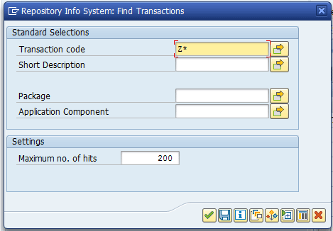
Enter Z* in the Transaction code search parameter in Figure 5 to get a list of all the Z (custom) transactions in the managed system. (Note: You might want to also search for Y* depending on the naming standards for your solution.)
When you execute the search by pressing Enter or clicking the enter icon ![]() , the results of the search are listed in a pop-up screen (Figure 6). By default, this list is limited to 200 items for performance reasons. If your system has more than 200 custom transactions, click the New Selection button to change the Maximum no. of hits parameter of the search options.
, the results of the search are listed in a pop-up screen (Figure 6). By default, this list is limited to 200 items for performance reasons. If your system has more than 200 custom transactions, click the New Selection button to change the Maximum no. of hits parameter of the search options.
Select the transaction that you want to analyze or click the select all icon ![]() to select all the transactions found (Figure 6).
to select all the transactions found (Figure 6).
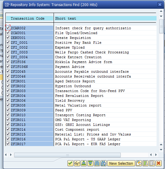
After you make your selections, click the enter icon. Solution Manager then retrieves the selected entries and populates the Transactions tab in your project (Figure 7).
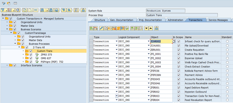
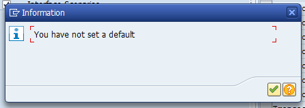
Choose any of the transactions to be the standard by clicking the radio button to the right of the transaction. This action enables you to avoid the warning message that you have not set a default, which is shown in Figure 8.
Save your project by clicking the save icon ![]() in the menu bar if you don’t have autosave turned on. Go to the SDA work center to create an analysis project using the selected transactions. Execute transaction code SM_WORKCENTER to open the SAP Solution Manager: Work Centers home screen.
in the menu bar if you don’t have autosave turned on. Go to the SDA work center to create an analysis project using the selected transactions. Execute transaction code SM_WORKCENTER to open the SAP Solution Manager: Work Centers home screen.
(Note: You need work center authorizations to access these work centers. For a list of the roles for the work centers use transaction code PFCG and search for *SMWORK*.)
From the home screen, navigate to the SDA Work Centers screen by clicking the Solution Documentation Assistant tab. If you don’t see the Solution Documentation Assistant tab, use the navigation menu ![]() on far right side of the tab strip.
on far right side of the tab strip.
Figure 9 shows the SDA Work Centers’ Analysis Projects view. From here, click the Create button to launch the Create Analysis Project guided procedure (Figure 10).
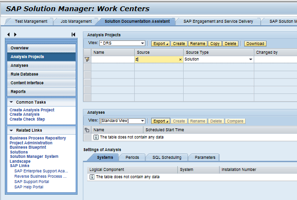
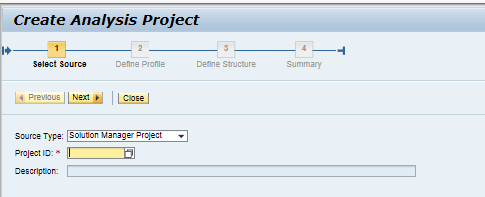
In the Source Type: field, choose Solution Manager Project for the parameter and enter your project name in the Project ID: field. Click the Next button. Enter a descriptive name in the Define Profile entry screen (Figure 11) and keep the defaults for the other parameters.
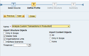
Click the Next button. In the Define Structure view in Figure 12, you can choose to include or exclude parts of the Solution Manager project from the analysis project you are creating.
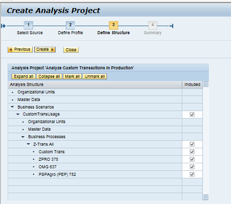
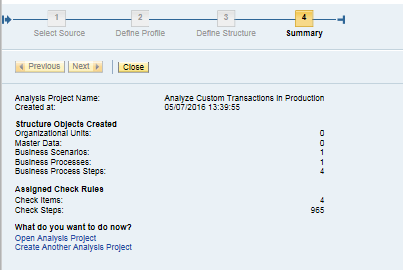
Click the Create button to display the Summary screen (Figure 13). This screen gives you a recap of the content of the newly created analysis project.
To run the analysis, return to the SDA Work Centers in the Analysis Projects view and select the newly created analysis project as shown in Figure 14.

When you select a particular Analysis Project (highlighted in orange in Figure 14), you have several options, including clicking the Create button. With the Create button, you can create an analysis using the newly created analysis project. An analysis is an executable instance of an analysis project. You can run any number of analyses for a given analysis project. This analysis is helpful when you are comparing different systems in the same landscape. For example, you might want to confirm that the training or quality assurance instances are the same as the production system. You can run a separate analysis for each of these systems and compare the results.
Click the Create button to launch the Create Analysis guided procedure to create a new analysis using the selected analysis project (Figure 15).
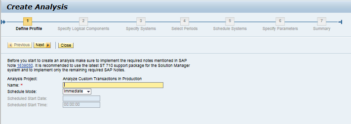
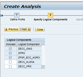
In the Name field enter a description for the analysis and click the Next button. The Specify Logical Components screen (Figure 16) lists the logical components assigned to the System Landscape tab of the project as it was defined in SOLAR_PROJECT_ADMIN. By default, the ones used in the project structure in SOLAR01 are already selected and cannot be removed.
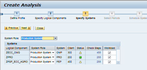
Click the Next button. In the Specify Systems (Figure 17) screen you can choose which system in the landscape is to be analyzed in this analysis. I chose Production System for my example. Click the Next button to proceed with the guided procedure.
The Select Periods screen (Figure 18) allows you to choose the time scope for the analysis. The Solution Manager SDA uses data logged in the managed system to perform its analysis. This data is compartmentalized into monthly buckets. Choose the time frame you wish to analyze and click the Next button.
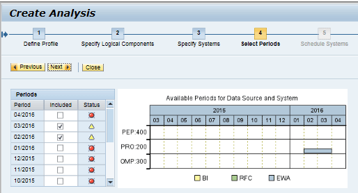
Note: Analyses can have a long run time if you choose a large number of months to analyze. For example, it took nearly 25 hours to run an analysis on a production system when it was run for a one-year scope. The impact on the analyzed system can be managed in the Schedule Systems step of the guided procedure and is described below (Figure 19).
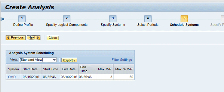
In the Schedule Systems screen, you can specify how the analysis should handle SQL Check Step Type rules. Because my example project does not have any SQL rules assigned, you can skip this step by clicking the Next button again.
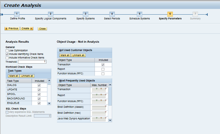
In the Specify Parameters screen (Figure 20), mark the Transaction check box under the Not Used Customer Objects parameter set to identify the custom transactions that are not used in the managed system.
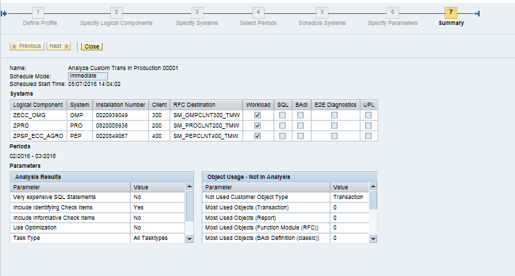
Next, click the Create button to display the analysis Summary screen shown in Figure 21.
In the Analysis Projects view of the SDA Work Centers screen, you should see your analysis running in the Analyses based on Analysis Project… pane in the screen shown in Figure 22. At the bottom right of the Analyses list, a line indicates when the view was last refreshed. Clicking this line refreshes the view.

Analyses generate a lot of valuable information about the managed systems being evaluated based on rules contained in an analysis project. An analysis project can contain many types of rules, one of which is the transaction rule. Since most productive solutions use a great many transactions, maintaining all the rules to analyze them can be cumbersome.
You’ve seen how to build a Solution Manager project that contains numerous transaction codes and then subsequently use it to accelerate the creation of an analysis project. Next, you saw how to create an analysis from the analysis project using a Solution Manager guided procedure, to direct the analysis to a particular system in the landscape, to set the scope of the analysis, and to control the run-time impact.
That’s a lot to take in. As always, take your time and set up some experiments to analyze your development or quality assurance systems before running against your production environments. You then can better understand how an analysis project gathers data and how running it affects the performance of your managed systems.


