The standard interactive planning table that ships with the Supply Network Planning (SNP) module in APO works just fine out of the box, but there's plenty of room for improvement. Fortunately, you can customize it in a number of ways that not only make it look terrific but also add value and functionality for planners.
Key Concept
The interactive planning table in SNP is the primary interface planners use to monitor their supply chain. It displays mission-critical information such as inventory levels, manufacturing and transportation schedules, and much more.
By adding new key figures, tweaking existing names, and making other modifications like elements that
change to indicate critical conditions, the interactive planning table in Figure 1 has been customized in
a way that makes the interface an even more useful tool. These changes are not difficult to make.

Figure 1
Customized SNP interactive planning table
I will show you how to adjust the SNP interactive planning table so it is easier to read as well as more
user friendly. Starting with the standard delivered planning book (9ASNP94) and the view SNP
PLAN, you can provide users with the enhancements and functionality that allow them to focus on areas that are
unique to your company.
Note
The enhancements in this article should be seen as suggestions that you can further modify to suit your individual requirements.
1. Create your own planning book. In most cases, custom planning books are set up at
implementation. If not, then you need to do so before you can customize your own planning book.
Note
Except where indicated otherwise, the menu paths described in this article are located in the APO tree structure.
Follow Supply Network Planning> Environment>Current Settings>Design Planning
Books or use transaction code /SAPAPO/SDP8B. Create a planning book (e.g.,
PBSNP) and data view (e.g., PBSNP(1)) by copying these with reference to the standard
book (9ASNP94) and data view (SNP94(1)).
Specify the newly created planning book PBSNP and click on Edit. In the
Planning book tab (Figure 2), rename the planning book in the Planning book
text field. Then repeat the process for data view 1 on the Data view tab. Select the Key
figures tab and click on Yes in the Planning wizard dialog box that asks
Should planning book and data view be completed? and save (Figure 3).

Figure 2
Planning book text field allows you to rename customized planning book

Figure 3
Dialog box in Planning wizard confirming customization
In the same transaction, select the Assign Planning Area option under
Edit. In the next pop-up screen, the system displays the first existing planning area alphabetically, not
the one currently assigned to the planning book. Select planning area 9ASNP02 and click on
Enter. Then click on Back and exit the transaction.
In the final step, follow Supply Network Planning>Environment>Current Settings>Macro
Builder or use transaction code /SAPAPO/ADVM. Select the planning book view PBSNP(1)
and click on Execute. Next click on Generate Macros, followed by
Back, and exit the transaction.
2. Rename key figures to suit your system. There is nothing wrong with the key figure
names that SAP uses, but they may not be in line with the vocabulary at your company. Moreover, it's not always clear what
the corresponding name in R/3 is for a certain object. While I can't offer you any hard-and-fast rules, the following
sample scenario should provide you with some food for thought when it comes to establishing a naming scheme that your
users will value.
After a deployment run, orders are sent to R/3 where they create purchase requisitions. SNP planning
results, however, are not transferred to R/3. You can rename the key figures DistrReceipt (Confirmed) and
DistrDemand (Confirmed) so that it is easier to understand what they are called in R/3. Remember, it's
often the small things that make the biggest impact.
Use transaction code /SAPAPO/SDP8B or follow menu path Supply Network
Planning> Environment>Current Settings>Design Planning Books. Specify planning book
PBSNP and click on Edit. Choose key figure 9AFSHIP (DistrReceipt (Confirmed)
) on the Key Figure Attributes tab and set the Free Text radio button. Next,
define the new name DistrReceipt (P/Req).
Now, select the key figure 9ADMDDF (DistrDemand (Confirmed)), and set
the Free Text radio button. Define the new name DistrDemand (P/Req Rel)
. Click on the Save Settings button, select the Key figures tab and click
Complete. As described earlier, click on Yes in the Planning wizard pop-
up box and save.
3. Make sure planning periods meet your requirements. The response time of an interactive
planning table is directly proportional to the number of periods shown in its grid. The more items in the grid, the longer
the response time. You should closely scrutinize the number of periods being displayed and create planning bucket profiles
with the optimum number of periods.
Follow the menu path Supply Network Planning>Environment>Current Settings> Maintain Time
Bucket Profiles for Supply Network Planning or use transaction code /SAPAPO/TR30. Enter the name
of the planning buckets profile in the Time buckets prfl ID field (PBP) and its description in the Short
text field (8 Weeks in Days) (Figure 4).

Figure 4
Define new time bucket profiles
Then press Enter on the keyboard. Type 8 in the first line of the Number
column and W in the Display Periodicity field. Pressing Enter again opens the second line of
the displayed table and populates the Basic Periodicity field by automatically matching the settings of
the Display Periodicity field in the first line. Again, set the Number field to
8 and in the second line enter T in the Display Periodicity column. Click on
save.
Now, select Supply Network Planning>Environment>Current Settings>Design Planning
Books or access the next screen via transaction code /SAPAPO/SDP8B. Specify planning book
PBSNP and click on the Edit button. On the Data View tab, set the
TB profile ID (future) field to PBP (Figure 5). Select the Data
view PBSNP(2) and repeat this last step. Continue to the last tab and click on the
Complete button. Once again, confirm the save query in the dialog box by clicking on
Yes.

Figure 5
Update the Data view tab with the new time bucket profile
Note
When generating a macro, the system considers the number of periods defined in the planning book using information in the time bucket profile. Because it has been changed, it is advisable to regenerate the macros using the new time bucket profile, otherwise you may receive incorrect results.
4. Hide non-essential key figures. In most cases, not all of the key figures
available are necessary. Key figures for joint production, for example, or those related to target stock
levels are somewhat extraneous because only a handful of companies use them. Others, such as the ATD receipts and ATD
issues key figures, don't need to be monitored because for the most part they only support background planning jobs. The
two key figures that I just noted are only used in a deployment planning run and do not require a place in your SNP
interactive planning table.
You can suppress the display of unwanted key figures rather than deleting them to avoid future problems if
you decide to display them later. Here's how to hide key figures related to stock levels.
Follow the path Supply Network Planning>Environment>Current Settings>Design Planning
Books or use transaction code /SAPAPO/SDP8B. Specify planning book PBSNP and
data view PBSNP(1) and Edit. Next, click on the Target Stock Level row,
and right-click on the same row to activate the context-sensitive menu (Figure 6). Chose Selected
rows in the menu and then Hide.

Figure 6
Right-click on a row to activate the context-sensitive menu to access settings
To make a row visible again, click on the name SNP PLAN located on the top left of the
screen. Right-click on the cell to activate the context-sensitive menu, and select Manage Hidden Rows. In
the upcoming screen, drag the rows you want to display from the Hidden Rows folder to the Shown
Rows folder (Figure 7).
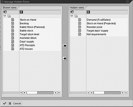
Figure 7
The Manage Hidden Rows screen allows you to display rows after they have been hidden
5. Refine the Days' supply key figure. The Days' supply key figure
displays the number of days that the current day's stock will last after all known future requirements and demands have
been factored in, such as forecast or actual sales. This key figure's shortcoming is that it rounds to the next full day,
and some industries require more precise forecasting. You can create a new unit of measure that adds one decimal to the
Days' supply value and use that instead of the SAP
supplied UoM.
In the mySAP SCM tree structure, select Tools>Customizing>IMG>Edit Project or
use transaction code SPRO. Click on the SAP Reference IMG button and select
General Settings>Check Units of Measurement. Select the Time dimension and click on
the Units of Measurement button. Press function key F7 (Create) and define the following
in the next screen:
| • Internal Unit of Measurement |
DS
|
| • Commercial Format |
DS
|
| • Technical Format |
DS
|
| • Decimal Places |
1
|
| • Numerator |
86,400
|
| • Denominator |
1
|
| • Measurement Text (Line 1) |
Days
|
| • Measurement Text (Line 2) |
Days
|
| • ISO Code |
Day
|
| • Commercial Measurement Unit |
"On"
|
On the keyboard, press Enter and confirm the onscreen warning message (ISO code DAY is already
used for measurement unit D) by pressing Enter again. Click on the save icon and the warning message will appear
again. You must confirm it again by pressing the Enter key. Exit the customizing transaction and return to the APO tree
structure.
Note
Because this definition is a customizing task, it may require a request number if your system requires change requests.
Select Supply Network Planning>Environment>Current Settings>Design Planning
Books or use transaction code /SAPAPO/SDP8B and specify planning book PBSNP.
Click on Edit, select the Key Figure Attributes tab, and choose the key figure
Cover to maintain the Days' supply value. Change the Unit of Measure
from D to DS. Click Save Settings and continue to the Key
Figures tab. Click on the Complete button and click on Yes in the dialog box to
save.
6. Add an Available Stock key figure. The main goal of every planner is to ensure that
enough stock is available at any time on any day. "Available stock" is defined as the projected physical stock minus the
safety stock requirements.
Unfortunately, no key figure exists for available stock. You can create one and make it so its field color
changes to reflect stock levels when displayed in the planning table. If, for example, the projected physical stock level
falls to zero or below, the color changes to red. Yellow indicates some projected physical stock remains, but it is below
the safety stock requirement. If you do not like displaying colors, you can still use the macro to calculate the available
stock. It can also be used to add a warning icon to the backlog key figure whenever a backlog exists.
Via transaction code /SAPAPO/SDP8B or following Supply Network Planning>
Environment>Current Settings>Design Planning Books, specify planning book PBSNP and click
on Edit. Select the Key figure attributes tab and type in the name of the new key figure
Available. Set the Free Text radio button and define the new name Available
Stock.
Then press the Enter key on your keyboard, set the UoM from product master flag and click
on the Save settings button. On the Key figures tab, drag the newly created key figure
AVAILABLE from the Planning book list on the right to the Data view
list on the left in the Assign key figures to data view area (Figure 8). Determine its
appropriate location within the list and place the new key figure in the desired position. Click on the
Complete button and confirm the settings by clicking on Yes in the dialog box noted
earlier.

Figure 8
Move the new key figure to the desired position of the Data view list
You have created the new key figure to display the available stock. Now let's define the algorithm to
calculate the available stock, and also the conditions under which the colors are set.
Use transaction code /SAPAPO/ADVM or follow Supply Network
Planning>Environment> Current Settings>Macro Builder. Select the planning book view PBSNP(1)
and click on Execute. Modify the existing macro Days' supply. Add the new step
Available Stock (Figure 9), then add Highlight Available Stock
(Figure 10) and click on Generate Macros to generate them. Click on the Back
button to exit the transaction.

Figure 9
Modify the Days’ supply macro by adding the Available Stock step

Figure 10
The second step added to the Days’ supply macro is Highlight Available Stock
7. Highlight non-working days. Monitoring multiple sites across an international supply
network requires accommodating workdays, holidays,
non-workdays, etc. that are not consistent in all locations. You can indicate non-workdays by displaying the
key figure Total Demand with a green background via a macro that uses is the shipping calendar defined in
the Location Master Calendar tab.
Use the transaction code /SAPAPO/ADVM or follow Supply Network Planning>
Environment> Current Settings>Macro Builder and select the planning book view PBSNP(1) and
click on the Execute button. Modify the existing Determine Workdays macro by adding the
new step Highlight Non-Workdays in the same way you modified Available Stock
(Figure 11). Click on the Generate Macros button to generate the macros. Then click on
the Back button and exit the transaction.

Figure 11
Modify the Determine Workdays macro by adding the Highlight Non-Workdays step

Wolfgang Eddigehausen
Wolfgang Eddigehausen is a highly experienced expert in the areas of business process design, re-engineering, and user adaption, as well as process realization in complex SAP-centric environments. He has experience in solution and enterprise architecture and project management (PRINCE2 certified) domains defining enterprise capabilities with a focus on delivering effective and efficient solutions to organizations. Wolfgang's industry knowledge includes public sector, utilities, mining, distribution, general manufacturing, process and steel industries, and consumer goods.
In most roles his task is not only to architect a solution but also to evaluate and define strategic options with a focus on end-to-end solutions rather than systems. This also includes strong emphasis on the user acceptance through an innovative user experience and mobility enablement.
His career includes successful participation and management of projects in Australia, Europe, India, Japan, Singapore, South Africa, Taiwan, and the US. These projects required interaction with all levels of an organization, from the shop floor or office through to the CxO level. Throughout his career, Wolfgang has put emphasis on a holistic approach bringing together people, processes, information, and systems in project management, architecture, and implementation roles.
You may contact the author at we@avox.com.au.
If you have comments about this article or publication, or would like to submit an article idea, please contact the editor.