At the moment, SAP Process Integration (SAP PI) does not support direct integration with the JavaScript Object Notation (JSON) format. Aaron Long shows how to develop a custom adapter module processor in Java to convert data between JSON and the XML format.
Key Concept
JavaScript Object Notation (JSON) is a lightweight data-interchange format. It is a programming-language-independent data format that is easy to read and write and for computers to parse and generate. It is widely used in Web applications to transmit data as an alternative to XML. Typically the JSON format is built on a universal structure as a collection of name/value pairs or an ordered list of values as an array, while the XML format is built on a tree-hierarchy-like structure with nodes, elements, values, and attributes within open and close tags. SAP Process Integration (PI) is enterprise application integration (EAI) middleware. Its key capacities in terms of connectivity, mapping, and routing are all developed and configured based on an XML format by means of messages. It provides varied adapters to connect systems or applications using different protocols and data formats.
As an alternative to XML, JavaScript Object Notation (JSON) is an open standard format that uses human-readable text to transmit data objects. It is widely used in applications in the cloud computing world (e.g., the online shopping applications running with a browser or mobile client). A frequent question is how an application using the JSON format can be integrated with an SAP system through SAP Process Integration (SAP PI) since SAP PI is XML based. This functionality is not currently provided as standard in SAP PI. This step-by-step guide for developing a custom adapter module shows how to address this function gap.
You can find the adapters currently offered by SAP via SAP Note 821268 (Adapter Framework: Overview of available FAQ notes) at
https://service.sap.com/sap/support/notes/821268. An adapter-supported JSON format application is not yet available.
The SAP PI Adapter Framework is an open platform based on the Web Application Server (Web AS) Java run time environment and the Connector Architecture (JCA). It allows you to develop a custom adapter module (user module or user exit) to handle the specific needs of data formatting and handling from/to source or target systems that are not able to be handled by the SAP standard adapters. After deploying the custom adapter module on your SAP PI system, the Adapter Framework module processors can use that module in the communication channel configuration by controlling the processing sequences.
I’ll walk you through the process of developing and testing a custom adapter module for handling the JSON format in SAP PI. When your Web application as the source system sends employee data in the JSON format, it looks like the Employees.json data shown in
Figure 1.

Figure 1
Data in JSON format (Employees.json)
However, your target application requires an XML data format that looks like the code in
Figure 2. For simplicity, I call this Staffs.xml data.

Figure 2
Data in XML format (Employees.xml)
In SAP PI, you need to define XML data corresponding to Employees.json and name it Employees.xml data. Its structure is like what you see in
Figure 3.

Figure 3
Data in XML format converting from the JSON format by SAP PI
You need to develop a custom module with SAP NetWeaver Development Studio (NWDS) and deploy it on SAP PI for the conversion from Employees.json to Employees.xml. Afterwards you can use SAP PI’s standard mapping functionality to map Employees.xml to Staffs.xml. Employees.xml uses lastName and firstName, while Staffs.xml uses fullName. The message flow in
Figure 4 fulfills such a business requirement with SAP PI.

Figure 4
End-to-end data flow
Following are the steps for developing a custom module:
- Define interface objects including Data Structure, Message Type, Service Interface, and Mappings in SAP PI Enterprise Service Repository (ESR).
- Develop a custom adapter module to convert JSON format to XML format in NWDS and have it deployed on the SAP PI system.
- Configure the integration scenario in SAP PI Integration Directory (ID) by using the interface objects from ESR and the custom adapter module.
- Test the scenario with SoapUI and verify the result.
Define Interface Objects in SAP PI ESR
Now I’ll describe the creation of all required interface objects for my test. The interface objects include:
- The data types of the sender interface and receiver interface.
- The mapping programs of the sender interface and receiver interface since they have different structures. These interface objects are used in the next section of this article.
1. Log on to the SAP ESR via the link https://<your_host>:<your_port>/rep. Locate your software component version. In my example, I am using software component Yi029837, version 1.0, which I created beforehand. Right-click Data Type and select the New button to create a new data type. That takes you to
Figure 5. Here you can create a data type representing the structure of Employee.xml.

Figure 5
Name the data type
2. Input the Name of the data type (Employees) and click the Create button, which takes you to
Figure 6.

Figure 6
Data type Employees
3. Define the data type Employees. Input all the elements of Employees.xml in this data type as shown in
Figure 6. Click the save icon to save the data.
4. Repeat the previous steps to create a data type named Staffs (
Figure 7), in which fullName is later used to map lastName and firstName.

Figure 7
Data type Staffs
5. Follow menu path Your Software component > your namespace, and right-click Message Types on the main screen of PI ESR. Click the New button to create message type MT_EMPLOYEES (
Figure 8). You refer to this message type in the next steps for message mapping and the service interface.

Figure 8
Create the Message type MT_EMPLOYEES
6. Input MT_EMPLOYEES and click the Create button, which takes you to
Figure 9.

Figure 9
Select data type Employees
7. Select Employees from the drop-down menu into the Data Type Used field in
Figure 9.
8. Click the save icon to save the message type.
Note
In the SAP PI system, the root element of the XML payload refers to the name of the message type. For example, the root element for Employees.xml is <ns0:MT_EMPLOYEES xmlns:ns0="https://agscoe.sap.com">. You need to make it configurable as an input parameter in the custom adapter module as shown in the following steps.
9. Repeat the previous steps to create message type MT_STAFFS, which is used for the receiver interface. That takes you to
Figure 10.
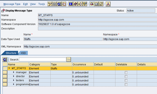
Figure 10
Create message type MT_STAFFS
Now go to the screen shown in
Figure 8 and select Service Interface. Input the interface name and click the New button to create a service interface. That takes you to
Figure 11. The service interface is used in the ID in the next section.

Figure 11
Create the sender interface
10. Input the name SND_SI_EMPLOYEES, which means a sender (SND) service interface (SI). Click the Create button since you are going to create an interface for the source system. That takes you to
Figure 12.
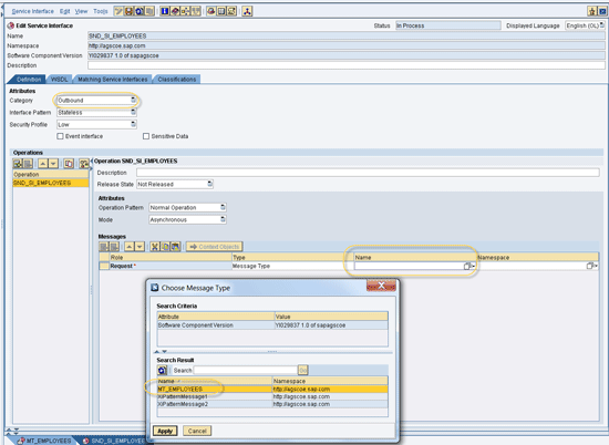
Figure 12
Choose the message type for the sender interface
11. Choose Category Outbound from the drop-down list in
Figure 12. Select Message Type MT_EMPLOYEES and click the Apply button. After that, leave the rest by default and click the save icon.
12. Repeat the steps above to create service interface RCV_SI_STAFFS for the target system. However, in this case, choose Inbound for the Category and MT_STAFFS as the message type name (
Figure 13) and save.
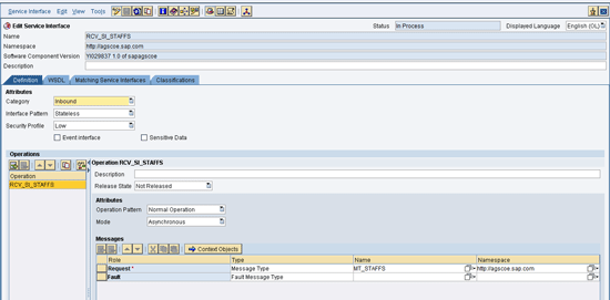
Figure 13
Create a service interface for the receiver
13. On the screen shown in
Figure 11, expand Mapping Objects. Right-click Message Mapping and click the New button to create a message mapping. The message mapping is to map the sender data structure and receiver data structure. That takes you to
Figure 14.

Figure 14
Create Message Mapping
14. Input the name MM_EMPLOYEES2STAFFS to create a message mapping to map data type Employees to data type Staffs. Click the Create button to go to
Figure 15.

Figure 15
Map the fields of the sender and receiver data structure
15. Select MT_EMPLOYEE as the source structure and MT_STAFFS as the target structure (
Figure 15). From MT_EMPLOYEES, simply concatenate firstName and lastName with a space in between and map it to fullName of MT_STAFFS. Click the save icon after you complete this step.
16. Go back to the
Figure 14 screen, right-click Operation Mapping, and click the new icon to create a new operation mapping by using the created service interface. That takes you to
Figure 16. This refers to the Message Mapping created in the last step. An operation mapping always refers to a message mapping, XSLT mapping, or Java mapping program.

Figure 16
Create Operation Mapping
17. Input the name OM_EMPLOYEES2STAFFS and click the Create button. That takes you to
Figure 17.

Figure 17
Input service interfaces and Message Mapping for operations mapping
18. Input service interface SND_SI_EMPLOYEES as the source operation and service interface RCV_SI_STAFFS as the target operation (
Figure 17). Input message mapping MM_EMPLOYEES2STAFFS as the mapping program and then save it.
19. On the main screen (not shown), click the Change Lists tab. Select the created objects including data type, message type, message mapping, and service interface. Click the Activate button to activate them (
Figure 18). Now the objects in the ESR are activated and ready for use by the Integration Directory in the next steps.
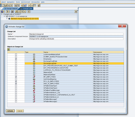
Figure 18
Activate interface objects
Develop and Deploy the Custom Adapter Module for JSON and XML Conversion
Now you use the following steps to develop a custom adapter module to convert JSON to XML format. I am using the Java library from json.org. However, you can use any JSON library as your preference. Refer to
https://www.json.org/.
1. Download the Java source code (
Figure 19) from
https://github.com/douglascrockford/JSON-java.
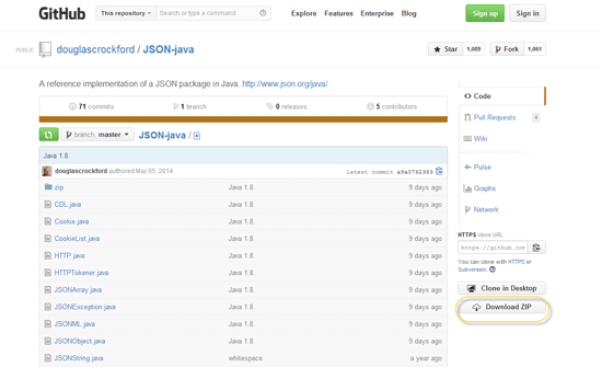
Figure 19
Download page of json.org
2. Unzip JSON-java-master.zip and copy all the source code to directory orgjson (
Figure 20).

Figure 20
File system structure of the Java library from json.org
Open SAP NWDS. Follow menu path File > New > Java Project, which takes you to
Figure 21.
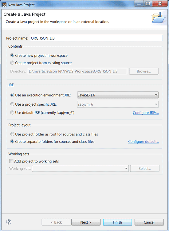
Figure 21
Create a Java project
3. Input the project name ORG_JSON_LIB. Select the Create new project in workspace radio button and then click the Finish button, which takes you to
Figure 22. NWDS creates the project ORG_JSON_LIB using a default setting. Right-click the src folder under the ORG_JSON_LIB project. This opens the Properties for src pop-up window where you may check the properties to find the location for the source code. It is D:myarticleJson_PINWDS_WorkspaceORG_JSON_LIBsrc, as shown in
Figure 22.

Figure 22
Find the project source code location
4. Copy the whole folder as shown in
Figure 20 (including structure orgjson from your unzip in step 2) to this location. Press F5 and now you can see that the source code from the folder org.json is loaded (
Figure 23).

Figure 23
The source code of org.json
5. Follow menu path Select Project > Build Project to go to
Figure 24 to compile the source code. All the Java source code under this project is compiled.

Figure 24
Compile the classes of org.json
6. The classes are output in …ORG_JSON_LIBbinorgjson. The classes refer to the Java classes under org.json such as CDL.java or Cookie.java. Correspondingly the CDL.class and Cookie.class are generated automatically by this Build Project action. Open a DOS prompt as shown in
Figure 25. Go to directory…ORG_JSON_LIBbin, and run command jar –cvf ORG_JSON_LIB.jar * to assemble all classes to file ORG_JSON_LIB.jar for future usage. Copy this to your…moduleLib directory.

Figure 25
Assemble json.org classes to a jar file
7. Prepare the SAP PI Java libraries that will be referred by your custom adapter module in the next step. You can find and copy the library files in the following folders in the existing SAP PI system with a pure Java stack under directory /usr/sap/<SID>/J00/j2ee/cluster/bin:
com.sap.aii.af.lib.mod.jar: /ext/com.sap.aii.af.lib/lib
sap.com~tc~logging~java~impl.jar: /system
com.sap.aii.af.svc_api.jar: /services/com.sap.aii.af.svc/lib
com.sap.aii.af.cpa.svc_api.jar: /services/com.sap.aii.af.cpa.svc/lib
com.sap.aii.af.ms.ifc_api.jar: /interfaces/com.sap.aii.af.ms.ifc/lib
You can put them together with ORG_JSON_LIB.jar in …moduleLib directory as shown in
Figure 26. Copy all the files to the same directory …moduleLib.
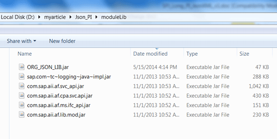
Figure 26
moduleLib file directory structure
Note
You can also download the .sca file of XI Adapter Framework from
https://service.sap.com/swdc, via menu path Support Packages and Patches > N > SAP NETWEAVER > SAP EHP1 FOR SAP NETWEAVER 7.3 > Entry by Component > PI Adapter Engine (Java EE) >XI ADAPTER FRAMEWORK 7.31. Then extract the library files from the sca file.
8. Add the library files to the classpath of your NWDS. Follow menu path Window > Preferences > Java > Classpath Variables > New > Folder to go to
Figure 27. Browse to the …moduleLib folder, input the Name PI_AFW_LIB_JSON_LIB, and click the OK button. This takes you to
Figure 28.

Figure 27
Add modulelib to your classpath

Figure 28
The added Classpath Variables
9. The classpath should look like
Figure 28 after it is configured as shown in
Figure 27.
10. Create the EJB and EAR projects for the custom adapter module. Follow menu path File > New > Project. Then select EJB Project and click the Next button.
11. Input the Project name JSONXMLUserModule and select the Use default and Add project to an EAR check boxes. (The latter selection enables you to use the default EAR project name created automatically.) Click the Finish button to complete the creation of the EJB and EAR projects using the default setting. That takes you to
Figure 29.
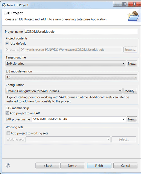
Figure 29
Create an EJB Project
12. Add the Java library files from the created class variable PI_AFW_LIB_JSON_LIB to the EJB project. Right-click JSONXMLUserModule and follow menu path Build Path > Configure Build Path, which takes you to
Figure 30.

Figure 30
Add Classpath Variables to the project
13. Switch to the Libraries tab on
Figure 30. Click the Add Variable… button, then Select PI_AFW_LIB_JSON_LIB, and click the Extend button. In the pop-up Variable Extension window, select all the jar files and click the OK button.
14. You can see now all the jar files are added to the libraries (
Figure 31). Click the OK button to complete it. It takes you to
Figure 32.

Figure 31
JARs and class folders on the build path

Figure 32
Create a package name for Java classes
15. Right-click ejbModule, select New > Package, input the Name com.sapagscoe.pi.adaptermodule, and click the Finish button, which takes you to
Figure 33.

Figure 33
Create Session Bean
16. Right-click com.sapagscoe.pi.adaptermodule. Follow menu path New > Session Bean. Input the Class name JSONXMLModuleBean. Uncheck the options under Create business interface. I am using the existing one so I don’t need to create one. Click the Finish button to create the custom module EJB class. That takes you to
Figure 34. At the beginning the source code part is empty.

Figure 34
Develop your source code for the custom module
17. Double-click JSONXMLModuleBean.java and start to develop your custom adapter module Java code here as shown in
Figure 34. See the sidebar “Develop a Custom Adapter” for more detail.
Develop a Custom Adapter
To see how to develop adapters and modules for SAP PI, refer to “Developing Adapters and Modules” from the SAP Help portal:
https://help.sap.com/saphelp_nw73/helpdata/en/8b/895e407aa4c44ce10000000a1550b0/content.htm?frameset=/en/87/3ef4403ae3db12e10000000a155106/frameset.htm. The sample source code is also available.
You must implement the Java interface com.sap.aii.af.lib.mp.module.Module and javax.ejb.SessionBean in your custom adapter module. You implement your custom logic in the method process, which inherits from the interface com.sap.aii.af.lib.mp.module.Module.
In my example, I use the private method Json2XML to convert the JSON format to an XML format and the private method XML2Json to convert XML to the JSON format.
Table A shows the configurable parameters for this custom module.
| Parameter name |
Description |
| xmlRootTagName |
Optional; json.org lib will generate the xml using this as root element. |
| convertDirection |
Mandatory; JSON2XML or XML2JSON. |
| Mandatory: JSON2XML or XML2JSON |
Mandatory; the message type you define in SAP PI ESR. |
| msg_namespace |
Optional; the XML namespace you define in SAP PI ESR. |
| xmlEncoding |
Optional; the XML encoding is used. UTF-8 is used as default. |
Table A
Parameters of the custom module
You can find all source code of JSONXMLModuleBean.java
here.
18. Configure the EJB Deployment Descriptor as shown in
Figure 34. Double-click Deployment Descriptor: JSONXMLUserModule and the ejb-jar.xml file opens on the right pane, taking you to
Figure 35. Remove ejb-client.jar from ejb-jar.xml and delete the project JSONXMLUserModuleClient since you won’t use them. They are not necessary since the custom module runs on the server side.

Figure 35
Configure the EJB Deployment Descriptor
Note
You can find the full source code of ejb-jar.xml
here. The purpose of the source code is to allow readers to use this project directly. The project includes the source code of the program and configurations for deployment of the program.
19. In the same screen as shown in
Figure 35, right-click display-name, Add After, and enterprise-beans (
Figure 36). That takes you to
Figure 37.

Figure 36
Add enterprise-beans

Figure 37
Configure EJB session bean name
20. Double-click session, expand the session (ejb-name), and input the ejb-name as JSONXMLCustomAdapterModule. Right-click ejb-name in
Figure 37 to go to
Figure 38. Select Add After > post-activate - transaction-type. Maintain the session-type as Stateless and the transaction-type as Container.
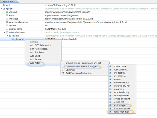
Figure 38
Maintain the ejb transaction and session types
21. Right-click ejb-name again to maintain other properties of the session bean, as shown in
Figure 39.

Figure 39
Maintain the properties of the ejb
22. The final result of the descriptor in ejb-jar.xml should look like
Figure 40.

Figure 40
Final result of the ejb-jar.xml
23. Double-click the file ejb-j2ee-engine.xml under the same directory of ejb-jar.xml to open it. Right-click the ejb-j2ee-engine node, and then follow menu path Add Child > enterprise-beans (
Figure 41).

Figure 41
Add enterprise-beans in ejb-j2ee-engine.xml
24. Input the values for ejb-name and jndi-name, which should look like
Figure 42, which is included just for reference purposes.

Figure 42
Define ejb-name and indi-name
Note
You can find the full source code of ejb-j2ee-engine.xml
here. The jndi-name is referred in the communication channel when configuring the module processors on your SAP PI system. You input the jndi-name in the communication channel as the module processor name later on.
25. Generate the deployment descriptor for the EAR project. Right-click Deployment Descriptor: JSONXMLUserModuleEAR as shown in
Figure 43. Select Generate Deployment Descriptor Stub. This is part of the J2EE application used in the next step.
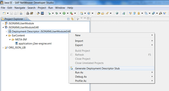
Figure 43
Generate the Deployment Descriptor Stub
26. The application.xml file is generated under the …/META-INF directory. The result should look like
Figure 44.

Figure 44
The deployment description of the application
Note
You can find the full source code of application.xml
here.
27. Open application-j2ee-engine.xml and right-click the top node to configure the reference, start-up, and module-additional properties as shown in
Figure 45.

Figure 45
Configure the start-up option
28. Switch to the Source tab for application-j2ee-engine.xml. The final result should look like
Figure 46.
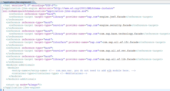
Figure 46
Final result of application-j2ee-engine.xml
29. Set up the SAP AS Java target server for the deployment. Follow menu path Window > Preferences > SAP AS Java > Add (
Figure 47). Input the instance information of your SAP PI system and click the OK button to complete this step.

Figure 47
Set up your target SAP AS Java server
30. Deploy the custom adapter module on your SAP PI system main screen (
Figure 48). Right-click JSONXMLUserModuleEAR. Select Run As > Run on Server.
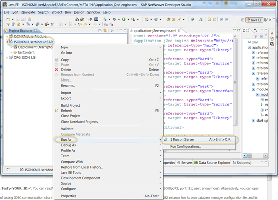
Figure 48
Deploy the custom module on the server
31. Choose your server (
Figure 49) and click the Next button.

Figure 49
Choose your server to deploy
32. Now you see your EAR project in
Figure 50. Click the Finish button to trigger the deployment on your server.

Figure 50
Deploy the EAR project
33. You see the result in the Deployment View Console upon deployment (
Figure 51).

Figure 51
Deployment displayed
Now your custom adapter module for JSON to XML (and vice versa) is ready for use on your SAP PI system.
Configure an Integration Scenario in SAP PI Integration Directory
Now I demonstrate how to configure an integration scenario in SAP PI ID by using the interface objects I created in ESR and the custom adapter module I deployed on the SAP PI system.
1. Log on to the SAP PI ID. Right-click Configuration Scenario and select the New button to create a new scenario. That takes you to
Figure 52.
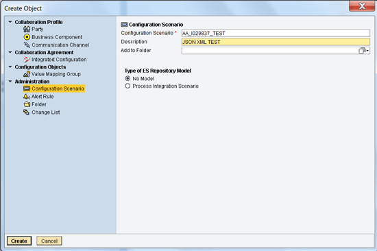
Figure 52
Create the configuration scenario
2. Input the name and description for your configuration scenario and click the Create button. I am using the default option.
3. In the screen that appears, click the Save button. This opens the screen at the rear of
Figure 53. Click the Objects tab and click the Create button to create sender communication component SND_I029837 as the source system. The source system is also known as the sender system in an integration scenario of PI.

Figure 53
Create the sender system
4. Click the Create button in
Figure 53, which opens on the Receiver tab of
Figure 54 (not shown). Then click the Sender tab to open the screen in
Figure 54, where you assign Interface SND_SI_EMPLOYEES from the list. You use this interface in the next step.

Figure 54
Add a sender interface
5. Click the save icon in
Figure 54 to save the created Communication component and assigned interface. It takes you to
Figure 55. Under the Communication Channel tab, click the create object icon and input communication channel name SND_HTTP in the pop-up window. Click the circled Create button in
Figure 55 to create a channel under component SND_I029837. It takes you to
Figure 56.

Figure 55
Create the sender communication channel

Figure 56
Configure the HTTP_AAE channel
6. Select HTTP_AAE from the adapter type list in
Figure 56 and click the Apply button. This takes you back to the screen to the rear of
Figure 56, where you click the save icon (circled) to save the created communication channel. This opens the screen in
Figure 57. Note that before you select HTTP_AAE and click the Apply button, the screen in
Figure 56 is empty.

Figure 57
Set the Payload parameter name
7. Use parameter JSONPayload for the HTTP request (
Figure 57) and save it. Switch to the Module tab in
Figure 56, which takes you to
Figure 58. Note that the save icon turns gray, which indicates that the modificaiton is saved.
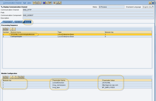
Figure 58
Configure module parameters
8. On the Module tab shown in
Figure 58, click the plus icon to add the custom module. The new module is appended automatically. It turns to gray after you save it. Click the up arrow to switch the sequence since you need to convert the JSON format data to XML before the data goes into PI. Use the module name JSONXMLCustomAdapterModule and type Local Enterprise Bean, which you have deployed on the system. Input parameter names and values appear as shown in the bottom of
Figure 58.
9. Repeat the steps to create receiver component RCV_I029837 (
Figure 59). However, in the Receiver tab, select interface RCV_SI_STAFFS and create channel RCV_FILE_XML using File Adapter type. Save the file to a directory (e.g., directory D:FTP_HOMETMP with the file name rcv_fromJSON.xml) as shown in
Figure 60. Repeat steps 5 and 6, but select the receiver channel.
Figure 60 is to show how the receiver channel looks like after it is configured.

Figure 59
Configure the receiver interface and channels

Figure 60
Configure the receiver channel directory
10. Go back to the Configuration Scenario by switching to the tab shown in Figure 61, Select the configuration scenario icon. Click the create object icon. Then select Integrated Configuration. For Sender information, input SND_I029837 as the communication component and interface SND_SI_EMPLOYEES. Click the Create button in
Figure 61 to go to
Figure 62.

Figure 61
Create an Integrated Configuration
11. In the Inbound Processing tab in
Figure 62, input SND_HTTP as the sender Communication Channel. You get to
Figure 62 via a redirect from
Figure 61. Although you can save it at any time, you may get a warning message when not all of the following steps are completed.

Figure 62
Input sender information
12. In the Receiver tab, input RCV_I029837 as the receiver Communication Component (
Figure 63).

Figure 63
Input the Receiver Component
13. In the Receiver Interfaces tab in
Figure 64, select OM_EMPLOYEES2STAFFS as the Operation Mapping and RCV_SI_STAFFS as the interface Name from the drop-down list as inputs.

Figure 64
Choose receiver interface information
14. In the Outbound Processing tab shown in
Figure 65, select RCV_FILE_XML from the drop-down list as the receiver Communication Channel. Don’t forget to click the save icon (circled in
Figure 65) to save all your configurations.

Figure 65
Choose the receiver communication channel
15. Close all your open tabs, switch to the change list shown in
Figure 66, and activate all your changes in the ID by clicking the Activate button.

Figure 66
Activate your configuration
Test the Scenario with SOAPUI and Verify the Result
Next I demonstrate how to test the integration scenario using SOAPUI as a client tool to simulate the Web application to send out data in the JSON format.
1. From SOAPUI, select File > New REST Project (
Figure 67). Input the URI and click the OK button to create a REST project.

Figure 67
Input the URI of SAP PI
2. Right-click REST Project and select New Web TestCase (
Figure 68).

Figure 68
New Web TestCase
3. Input the URL of your plain HTTP communication channel in the Web Address field (e.g.,
https://cndt5008po73.pvgl.sap.corp:50000/HttpAdapter/HttpMessageServlet?interfaceNamespace=https://agscoe.sap.com&interface=SND_SI_EMPLOYEES&senderService=SND_I029837&qos=EO) in
Figure 69.

Figure 69
Input the URL of your HTTP channel
Enter the Web TestCase Name JSON2XML_PI and click the OK button to go to
Figure 70.

Figure 70
Maintain the username and password and the XML payload parameter
4. You may see an HTTP 401 error. Input the user name and password of your SAP PI system under the HTTP TestRequest Properties tab. Switch to the Request tab (on the right of
Figure 70). Click the + icon, input the payload parameter name JSONPayload that you defined from the communication channel, and click the OK button.
5. Copy and paste the Employees.json content to the Value field in
Figure 71. Click the green play icon to send the request to SAP PI.
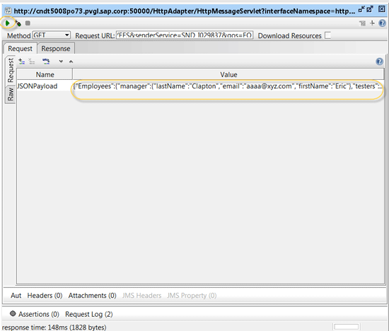
Figure 71
Input the JSON value
6. Log on to the SAP PI system to check the result via
https://<host>:<port>/nwa (
Figure 72). Follow menu path SOA > Monitoring > Communication Channel Monitor to go to
Figure 73.

Figure 72
Check the channel

Figure 73
Display the sender channel
7. Input SND_HTTP in
Figure 73 and click the Go button to locate your communication channel. It takes you to
Figure 74.

Figure 74
Incoming messages on the sender channel
8. Scroll down to the Memory Logs tab in
Figure 74 to review the list of the incoming messages sent to this channel in the last step.
9. Click the Message ID for the desired message in
Figure 74 to open the message in a new window. Scroll down and click the Outbound entry in
Figure 75. Click the Go button to load the message in
Figure 75. Click the Open Message tab to display the message in a new window. It takes you to
Figure 76.

Figure 75
Display a message
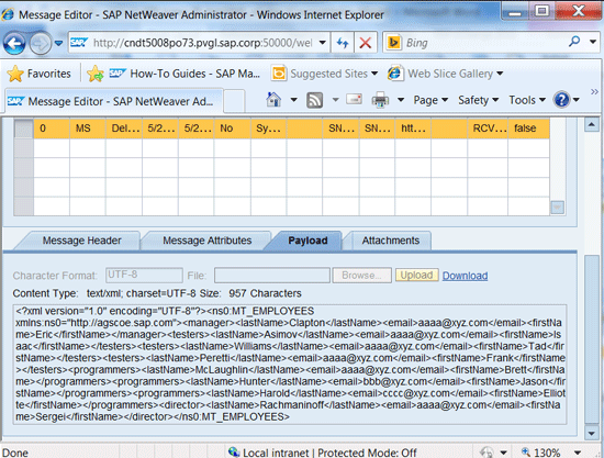
Figure 76
Display the XML payload
10. Switch to the Payload tab in
Figure 76 and you see the XML message in SAP PI.
11. Alternatively, you can go to the file directory of your target system as per configuration in the receiver channel and open the XML file for checking as shown in
Figure 77.

Figure 77
The result on the receiver system
Aaron Long (Huaqiao Long)
Aaron Long is a senior SAP consultant specialist in SAP NetWeaver PI at SAP Active Global Support (SAP AGS). He is responsible for helping customers implement and operate their SAP solutions at their maximum potential and to manage their technical risks during solution implementation and operation. He has been working in SAP AGS for about 10 years.
You may contact the author at
aa.long@sap.com.
If you have comments about this article or publication, or would like to submit an article idea, please contact the
editor.


